Wedge drive with slide receptacle
A technology of sliding parts and drives, which is applied in the direction of manufacturing tools, presses, punching machines, etc., can solve the problems of complicated cost of clamping and guiding devices, achieve safe work, reduce the size of the structure, and reduce the effect of manufacturing costs
- Summary
- Abstract
- Description
- Claims
- Application Information
AI Technical Summary
Problems solved by technology
Method used
Image

Examples
Embodiment Construction
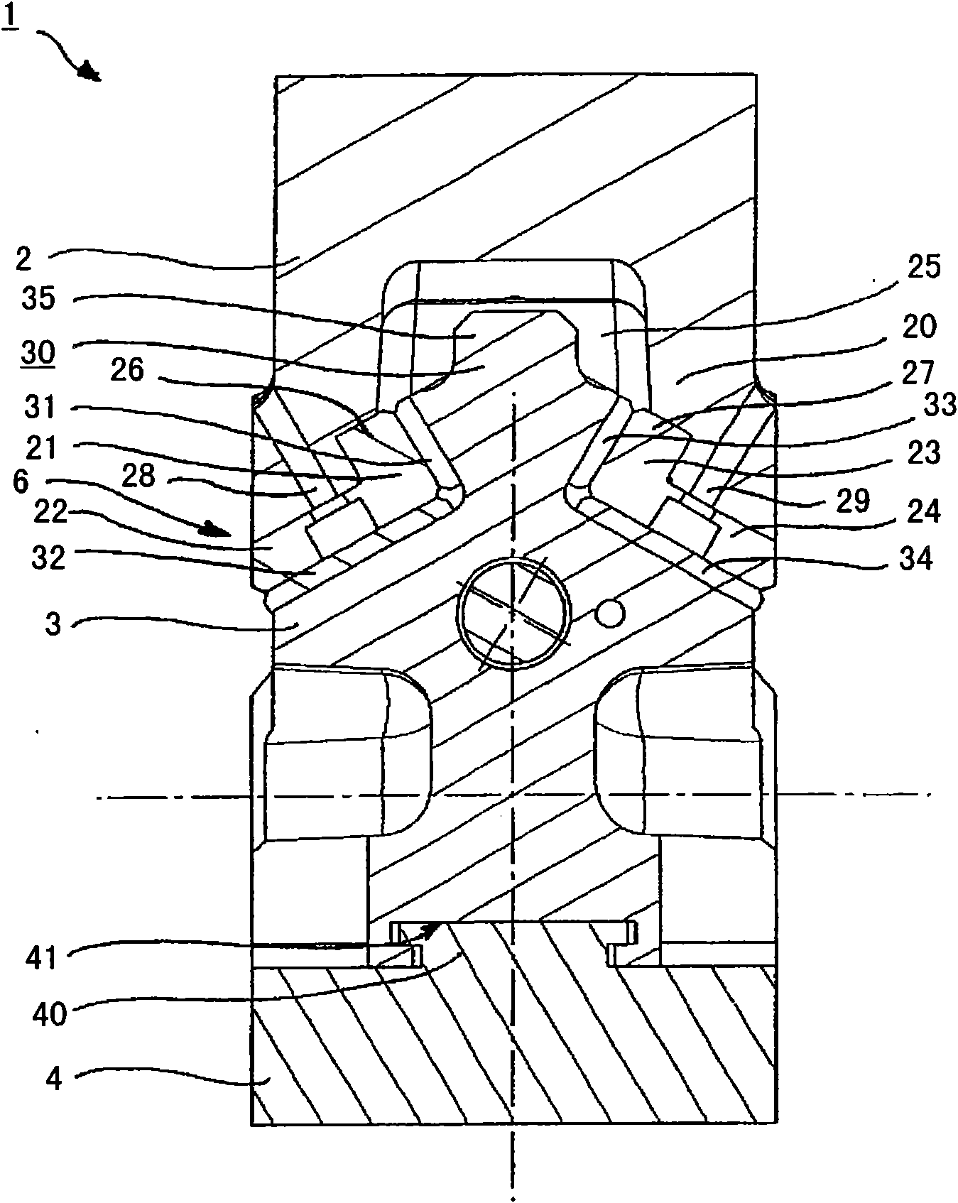
[0042] figure 1 A sectional view of a wedge driver 1 or cotter key is shown, comprising a slide receiver 2, a slide 3 and a receiver 4 for receiving a machining tool. The drive connected to slider 3 is infigure 1 not visible in , but in Figure 4 can be found in the perspective view of .
[0043] The slide and slide receiver are connected together by means of dovetail or prismatic guides 6 . In this case, the slide 3 has a portion 30 of a dovetail-like structure. It comprises two sliding surfaces 31 , 32 , 33 , 34 which are arranged on both sides at an angle to each other. In this arrangement, the two sliding surfaces 31 and 33 are smaller than the two sliding surfaces 32 and 34 . The reason for this is that during the working stroke the pressing force exerted by the pressing tool in which the wedge drive is arranged is transmitted from the slider receiver to the slide by means of the sliding surfaces 32 , 34 . During the return movement or the backward stroke (stroke) mo...
PUM
 Abstract
Description
Claims
Application Information
 - Generate Ideas
- Intellectual Property
- Life Sciences
- Materials
- Tech Scout
- Unparalleled Data Quality
- Higher Quality Content
- 60% Fewer Hallucinations
Browse by: Latest US Patents, China's latest patents, Technical Efficacy Thesaurus, Application Domain, Technology Topic, Popular Technical Reports.
© 2025 PatSnap. All rights reserved.Legal|Privacy policy|Modern Slavery Act Transparency Statement|Sitemap|About US| Contact US: help@patsnap.com