Paper cutter bed guide mechanism

A technology of guiding mechanism and paper cutting machine, which is applied in metal processing and other directions, can solve the problems of material cost, high processing cost, affecting normal production, unusable linear guide rail pairs, etc., and achieves the reduction and adjustment of processing accuracy and smoothness requirements The eccentric angle is light and flexible, and the effect of prolonging the effective working time

Active Publication Date: 2010-10-06
德阳市利通印刷机械有限公司
View PDF3 Cites 2 Cited by
  • Summary
  • Abstract
  • Description
  • Claims
  • Application Information

AI Technical Summary

Problems solved by technology

At the same time, the impact force may also cause deformation of the eccentric shaft, making it difficult to adjust the left and right heights of the knife bed
[0006] 3. Since the wear between the slider and the chute of the knife bed is inevitable, in order to protect the knife bed, the slider is designed as a wear part and can be replaced, but the replacement of the slider is very cumbersome. It is necessary to stop the machine and disassemble the main body. , sub-frame, use the hoisting tool to take out the knife bed to replace the slider on the main frame, which not only affects the normal production, but also takes time and effort, which is very inconvenient; moreover, the material of the knife bed and the machining accuracy and smoothness of the chute are very high. , otherwise there will be a large frictional resistance, so the material cost and processing cost are high
[0007] 4. The eccentric shaft is directly matched with the assembly hole on the tool bed. Due to the high precision of the fit, it is a transitional fit. It is laborious to adjust the eccentric angle, and it is difficult to adjust. It often requires multiple adjustments to make the left and right heights of the tool bed the same
However, due to the special structure of the paper cutter bed guide and the inseparable characteristics of the linear guide rail pair slider and the guide rail, it is difficult to assemble it in the paper cutter bed guide. At present, the linear guide rail pair is in the international market. , Domestic paper cutters have not been used in the direction of the knife bed

Method used


Image

  • Paper cutter bed guide mechanism
  • Paper cutter bed guide mechanism
  • Paper cutter bed guide mechanism

Examples


Embodiment Construction

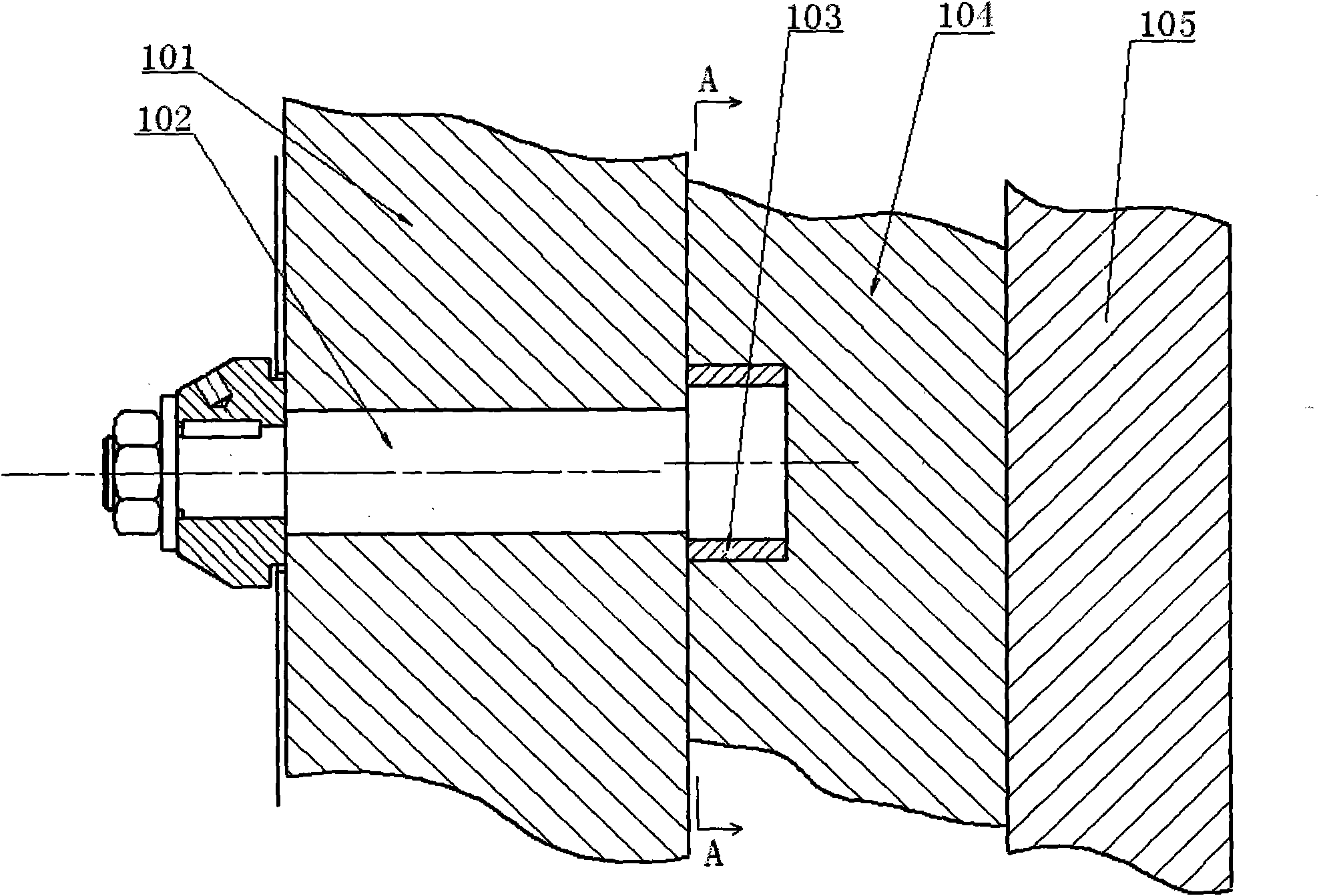
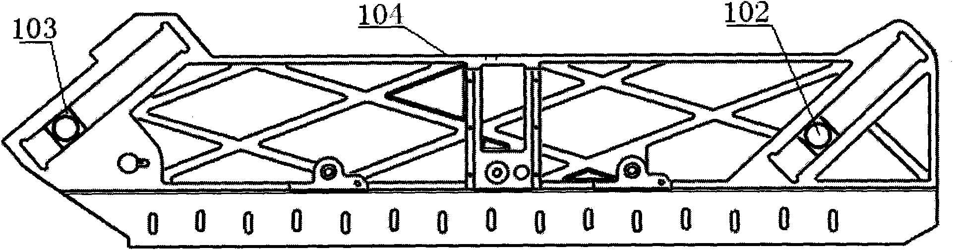
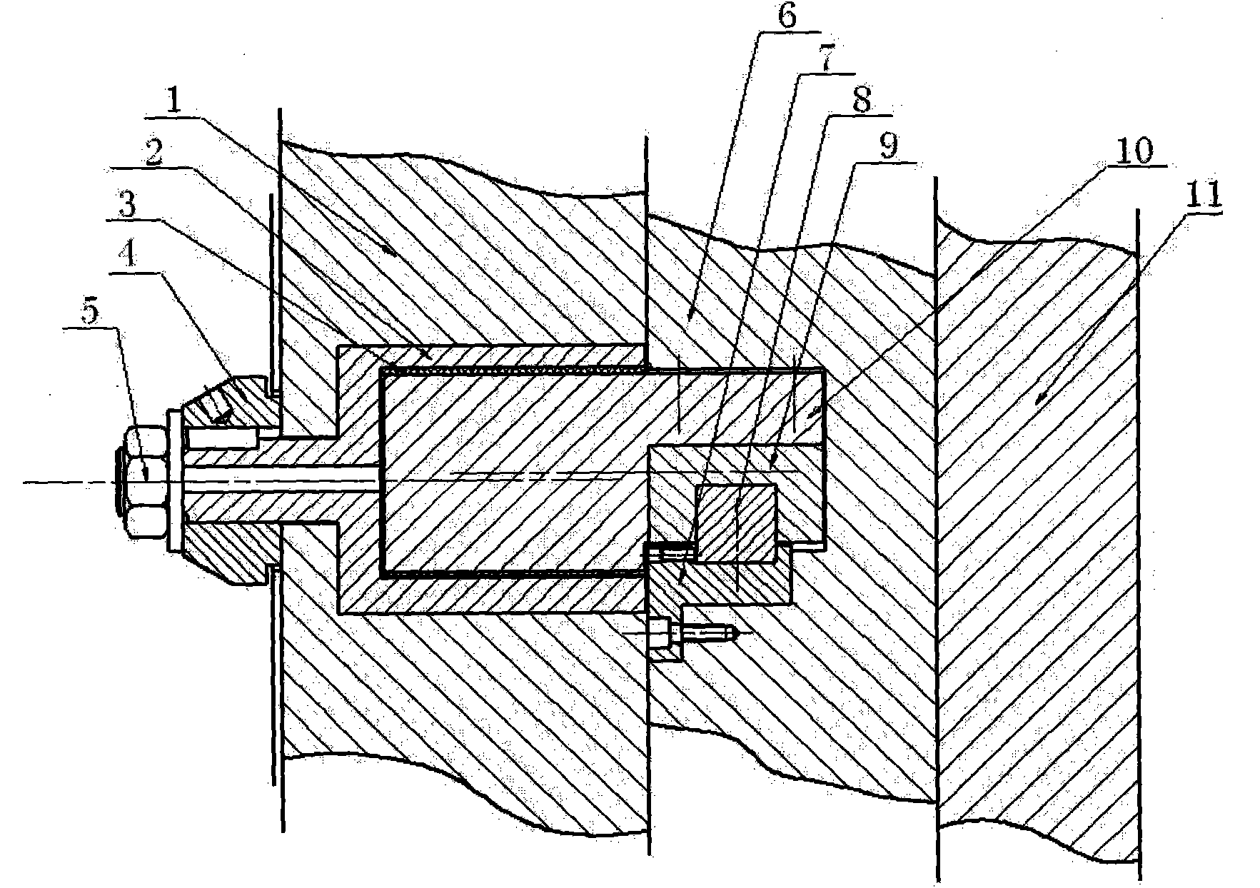
[0023] see image 3 The present invention comprises a main frame 1 and a sub-frame 11, a knife bed 6 is located between the main frame 1 and the sub-frame 11, and the two opposite surfaces of the knife bed 6 slide with the opposite faces of the main frame 1 and the sub-frame 11 respectively Cooperate.

[0024] There is a pair of assembly holes on the main frame 1, and the eccentric sleeves 2 are respectively installed in the holes. The eccentric sleeves 2 pass through the assembly holes on the main frame 1 and extend to the back of the main frame 1. An eccentric adjustment handwheel 4 that rotates synchronously with it is installed, and a nut 5 is arranged on the outside of the eccentric adjustment handwheel 4, and the eccentric sleeve 2 is locked and fixed in the assembly hole on the main frame 1 by the nut 5 . A connecting shaft 10 is housed in the eccentric sleeve 2, and the connecting shaft 10 is movably matched with the eccentric sleeve 2, and a bearing 3 is arranged bet...


PUM


Abstract

The invention discloses a paper cutter bed guide mechanism. The guide mechanism comprises a main rack and a secondary rack, wherein a bed is arranged between the main rack and the secondary rack, the two reverse surfaces of the cutter are respectively in slide fit with the opposite surfaces of the main rack and the secondary rack; the main rack is provided with a pair of pilot holes, and eccentric bushings are respectively arranged in the pilot holes and are locked and fixed in the pilot holes of the main rack by nuts; a connecting shaft is arranged in the eccentric bushing and is in clearance fit with the eccentric bushing; the bed is provided with a pair of chutes corresponding to the connecting shaft; a liner guide rail pair is arranged in the chutes; the slide block of the liner guide rail pair is fixed on the connecting shaft; a transition connecting block is fixed on the side surfaces of the chutes; and the guide rail of the liner guide rail pair is fixed on the transition connecting block. The invention has the characteristics of favorable wear-resisting performance, long service life, high operation precision, low noise, compact and simple structure, high processing efficiency, time and labor saving, low manufacturing and maintaining cost and the like.

Description

Technical field: [0001] The invention relates to a paper cutter, in particular to a knife bed guiding mechanism of the paper cutter. Background technique: [0002] see figure 1 , figure 2 The paper cutter of the paper cutter is installed on the knife bed 104, and the knife bed 104 is located between the main frame 101 and the sub-frame 105 of the paper cutter, and the front and rear directions are limited by the main frame 101 and the sub-frame 105, When the knife bed 104 is working, relative displacement occurs with the main frame 101 and the sub-frame 105, and its motion track is a curved reciprocating motion, not only vertical up and down reciprocating motions, but also horizontal left and right reciprocating motions. Compound motion of these two motions. Its guide mechanism is composed of main frame 101, subframe 105, eccentric shaft 102, and slide block 103. The main section of eccentric shaft 102 is installed in the assembly hole of main frame 101, and its eccentri...

Claims


Application Information

Patent Timeline
Patent Type & Authority Applications(China)
IPC IPC(8): B26D7/00B26D7/26
Inventor 熊伟光刘涛
Owner 德阳市利通印刷机械有限公司
Why Eureka
Try Eureka