Vertical landing lifting system of vertical landing plane

A vertical take-off and landing, lift technology, applied to the power plant, aircraft parts, machine/engine, etc. on the aircraft, can solve the problems of large invalid load, enlarged aircraft cross-section, ground erosion and erosion, etc., to simplify the structure and reduce invalid The effect of loading

Inactive Publication Date: 2010-10-06
余志刚
View PDF0 Cites 5 Cited by
  • Summary
  • Abstract
  • Description
  • Claims
  • Application Information

AI Technical Summary

Problems solved by technology

[0004] 1) The structure is complex: the vertical lift fan needs the largest clutch in the world to cooperate with the turbofan engine; two movable intake valves need to be set on the upper side of the fuselage to provide air intake passages for the vertical lift fan and the engine respectively;
[0005] 2) The invalid load is large during normal flight: the vertical fan lift system is invalid load during normal flight;
[0006] 3) Poor aerodynamic shape: the vertical fan lift system is located in the center of the fuselage, and the air intake air must bypass the vertical fan lift system, increasing the cross-section of the aircraft;
[0007] 4) The nozzle structure is complex: the tail nozzle needs three conduits and related drive systems in order to realize the vector conversion, so as to realize the conversion from horizontal flight to vertical thrust output
[0008] The problem of the Russian Yak-141 is similar to that of the American F-35B, and the independent lifting engine has serious erosion on the ground

Method used


Image

  • Vertical landing lifting system of vertical landing plane
  • Vertical landing lifting system of vertical landing plane
  • Vertical landing lifting system of vertical landing plane

Examples


Embodiment Construction

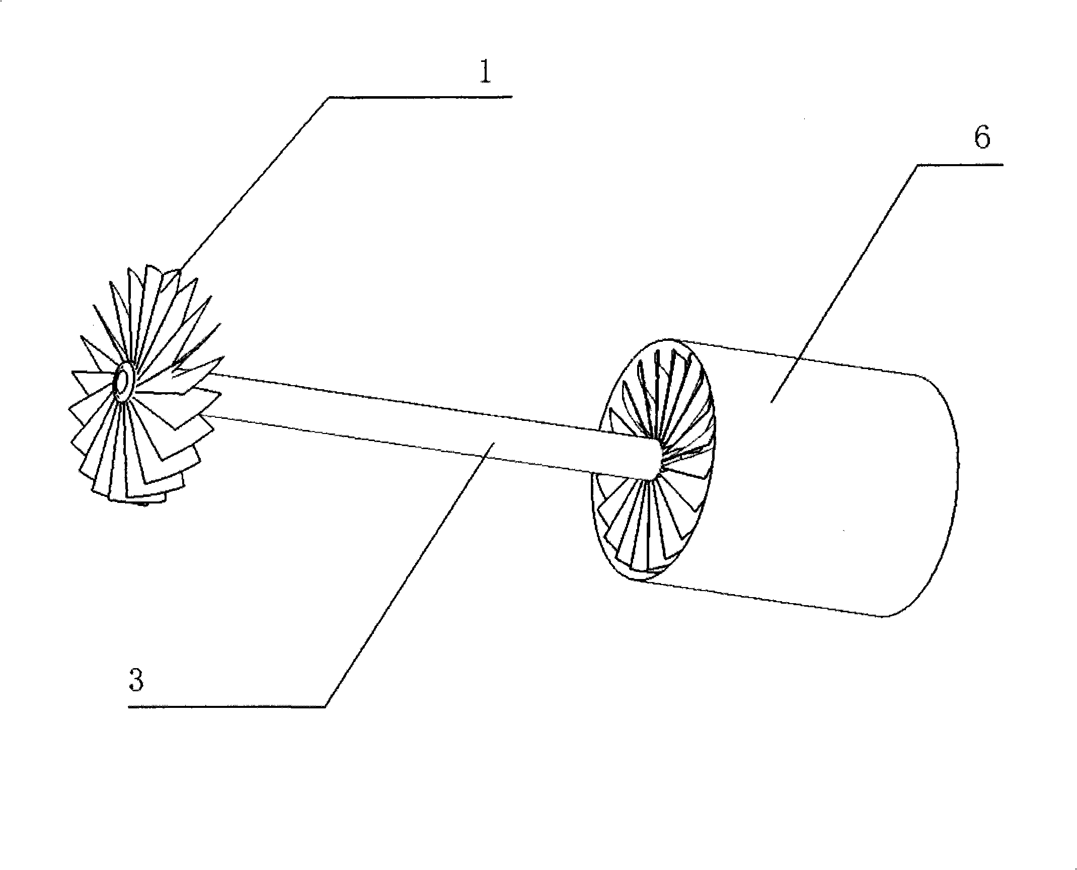
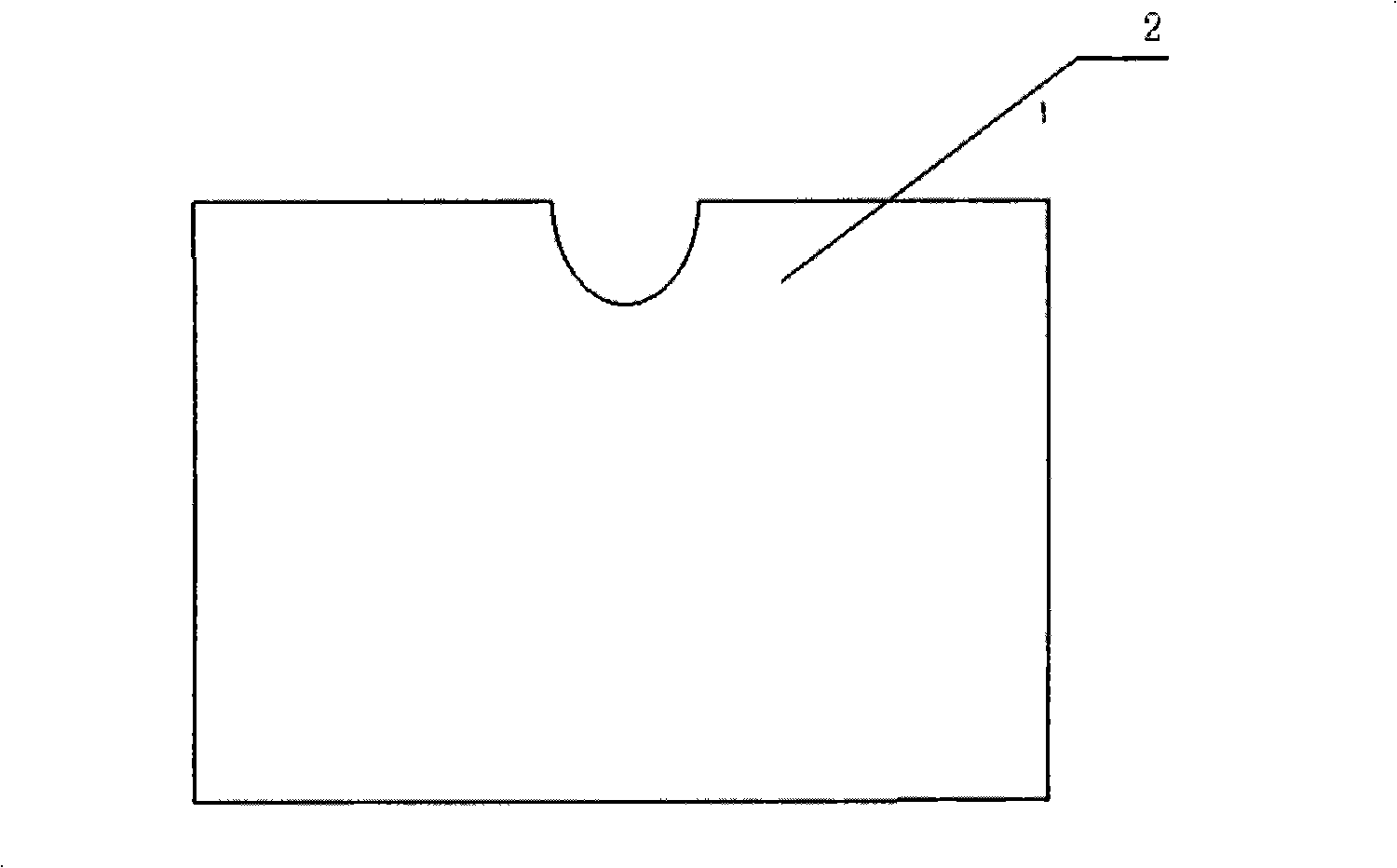
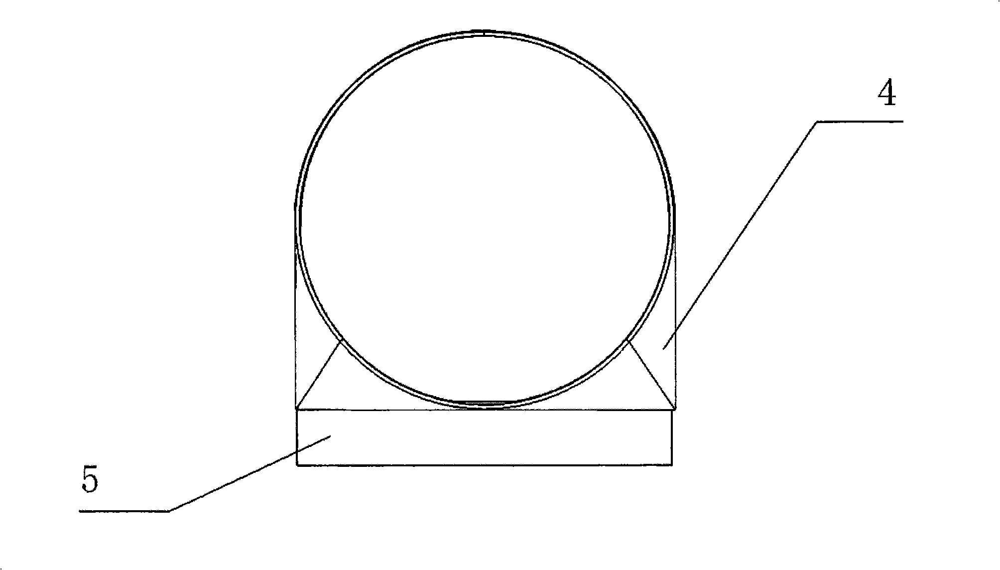
[0033] exist Figure 1 to Figure 16 Middle, 1. Front low-pressure fan, 2. Vector control guide plate, 3. PTO shaft, 4. Front air duct, 5. Down damper, 6. Turbo fan or turbojet engine, 7. Gas down damper, 8. Gas vector Control guide plate, 9. gas channel, 10. tail nozzle.

[0034] exist figure 1 Among them, the turbofan or turbojet engine (6) drives the power take-off shaft (3) to rotate, and the power take-off shaft (3) drives the front low-pressure fan (1) to rotate, and generates low-pressure propulsion airflow; the power take-off shaft (3) makes the front A certain distance is created between the low pressure fan (1) and the turbofan or turbojet (6).

[0035] exist figure 2 , the vector control guide plate (2) has a gap, so that the power take-off shaft (3) passes through without contact under the state of being at an angle of 45 degrees with the vector control guide plate (2).

[0036] exist image 3 Among them, the front view of the front air duct (4), the front air...


PUM


Abstract

The invention relates to a vertical landing lifting system of a vertical landing plane, and a space is generated between the front low pressure fan and the turbofan or the turbojet engine via the output shaft of the prolonged front low pressure fan. In the space, a front air channel and a vector control guide plate are arranged. Direction of a part of low pressure propelling airflow generated by the front low pressure fan is changed by changing the angle of the vector control guide plate. A gas channel and a gas vector control guide plate are arranged on the channel of jet gas airflow of the engine to change the direction of the jet gas airflow of the engine by changing the angle of the gas vector control guide plate. The angles of the vector control guide plate and the gas vector control guide plate are changed simultaneously so that the plane can achieve level flight and vertical landing state easily.

Description

technical field [0001] The invention relates to a vertical take-off and landing lift system for vertical take-off and landing aircraft, especially different from the known British "Harrier", American F-35B, and Russian Yak-141 vertical take-off and landing lift systems. Background technique [0002] At present, the known VTOL aircraft systems are the American F-35B, the British Harrier and the Russian Yak-141. [0003] The American F-35B drives the vertical fan lift system through the output shaft of the turbofan engine. The vertical fan lift system: [0004] 1) The structure is complex: the vertical lift fan needs the largest clutch in the world to cooperate with the turbofan engine; two movable intake valves need to be set on the upper side of the fuselage to provide air intake passages for the vertical lift fan and the engine respectively; [0005] 2) The invalid load is large during normal flight: the vertical fan lift system is invalid load during normal flight; [00...

Claims


Application Information

Patent Timeline
Patent Type & Authority Applications(China)
IPC IPC(8): B64D27/00F02K3/06
Inventor 余志刚
Owner 余志刚
Why Eureka
Try Eureka