
Debris flow guiding slot based on step anti-erosion toothed sill group and application thereof

An anti-scouring and debris flow technology, which is applied in the field of debris flow drainage channels, can solve the problems of providing sufficient guarantee for the stability of the side wall of the beam flow, potential safety hazards of the side walls of the drainage channel, and increasing the buried depth of the side wall foundation, so as to reduce erosion Destructive capacity, reduced operation and maintenance costs, and the effect of preventing ditch bed sedimentation

Inactive Publication Date: 2010-10-06
INST OF MOUNTAIN HAZARDS & ENVIRONMENT CHINESE ACADEMY OF SCI
View PDF7 Cites 14 Cited by
  • Summary
  • Abstract
  • Description
  • Claims
  • Application Information

AI Technical Summary

Problems solved by technology

But at the same time, the staggered tooth sills cause the debris fluid to flow around and dissipate energy in the groove. The existence of the flow around will bring some potential hidden dangers to the safety of the side wall of the drainage groove; Excessive flow energy dissipation can easily cause debris flow to deposit in the drainage channel. In view of the decrease in the slope of the ditch bed, the invention application adopts a method of reducing the length of the tooth sill to reduce the energy dissipation around the flow. However, because the tooth sill is on the beam side wall Therefore, as the length of the tooth sill decreases, the shorter the tooth sill, the less sufficient protection can be provided for the stability of the beam side wall. Therefore, it is necessary to increase the buried depth of the side wall foundation to solve the problem, but this will lead to too much cost increase

Method used


Image

  • Debris flow guiding slot based on step anti-erosion toothed sill group and application thereof
  • Debris flow guiding slot based on step anti-erosion toothed sill group and application thereof
  • Debris flow guiding slot based on step anti-erosion toothed sill group and application thereof

Examples


Embodiment 1

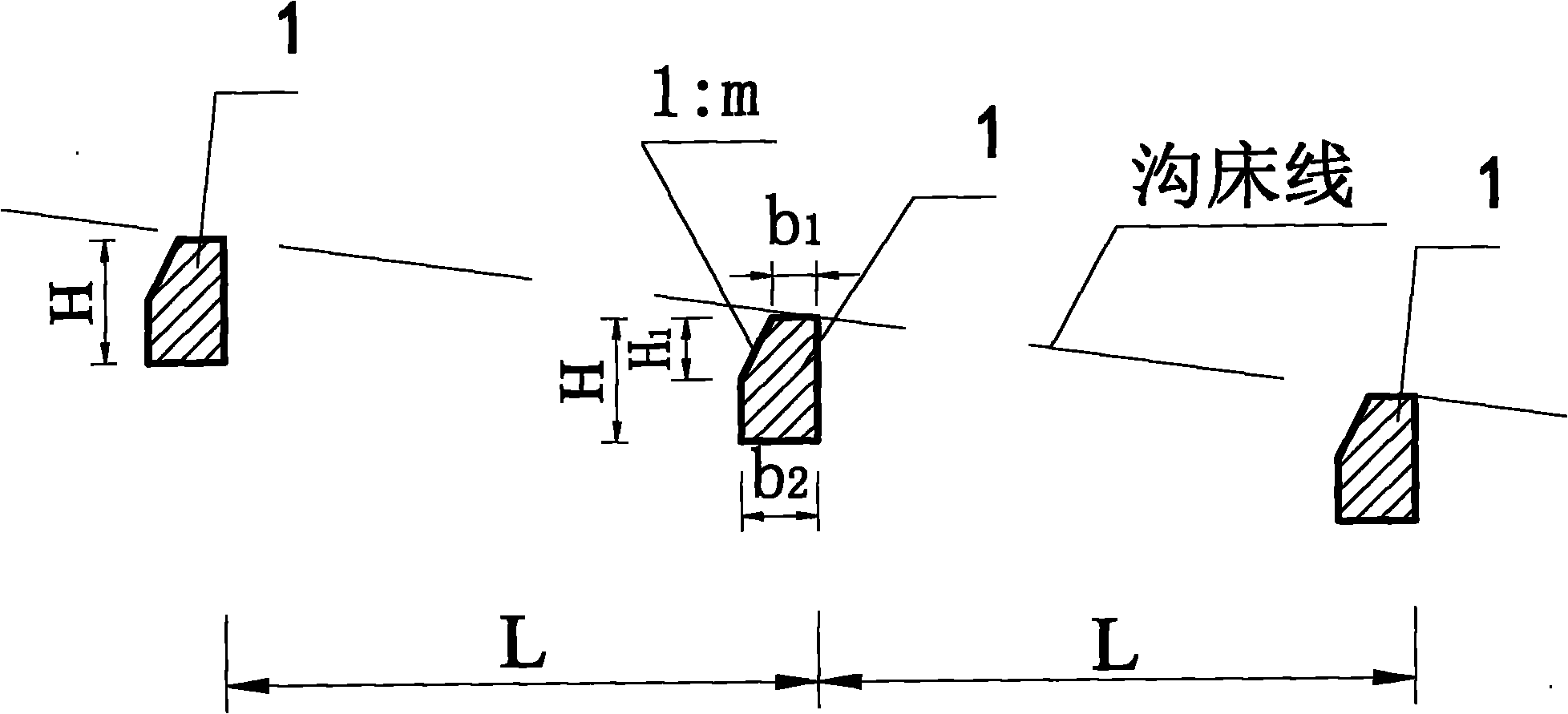
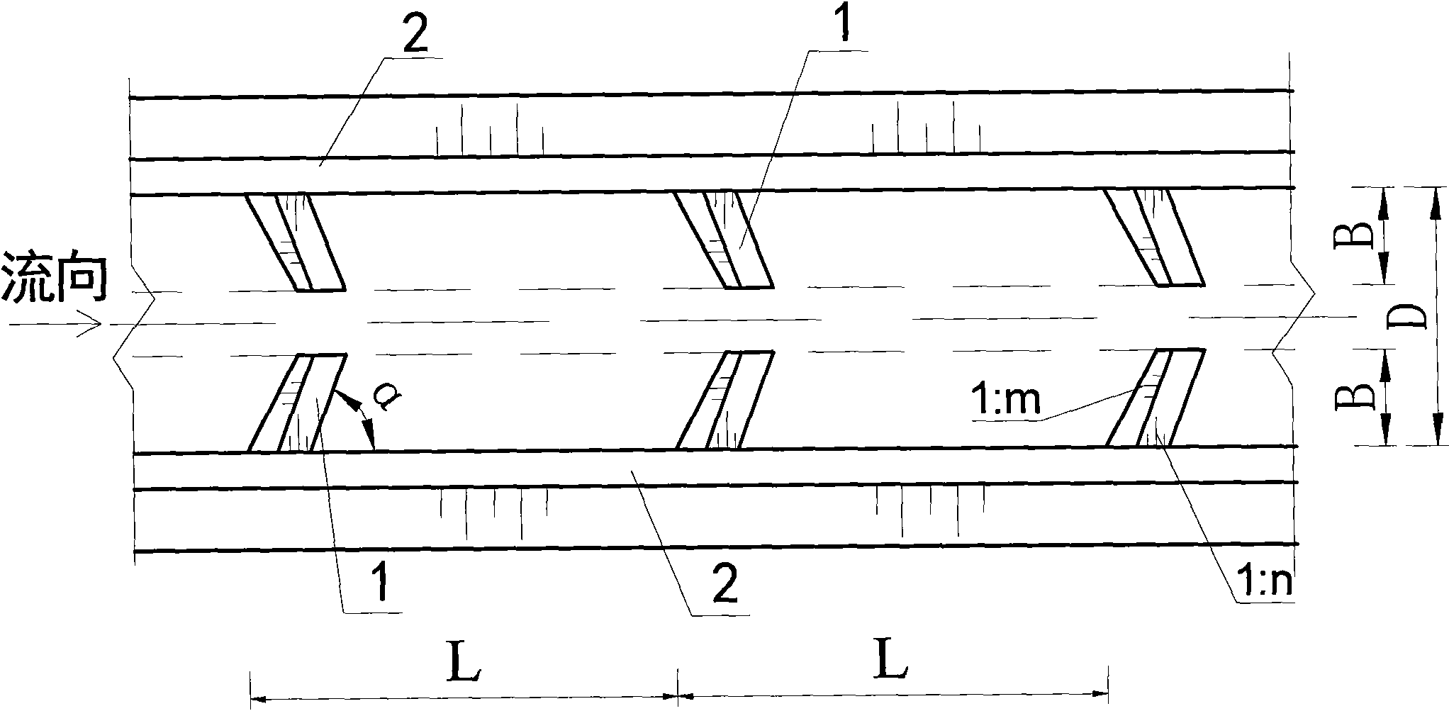
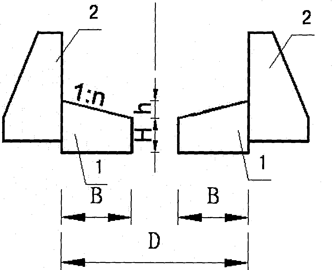
[0031] Such as figure 1 , figure 2 , image 3 shown. For a watershed area of ​​2.0km 2 , The slope of the accumulation fan (that is, the slope of the ditch bed) is 12%. Under the design standard, dilute debris flow, water-rock flow and flash flood are mainly considered. On the debris flow accumulation fan, the debris flow drainage channel based on the symmetrical stepped anti-scour tooth sill group includes the beam side wall 2 and the stepped anti-scour tooth sill group placed therebetween, connected to it, and used in conjunction with it. The step anti-scour Every two steps of the tooth sill group are distributed at a certain interval, and the step anti-scour tooth sill group is composed of several anti-scour tooth sills 1 with a certain buried depth. The distance L between every two steps of the anti-scour tooth sill group is 8.0m, and the buried depth H of the anti-scour tooth sill 1 is 2.5m.

[0032] The two anti-scour tooth sills 1 are symmetrically distributed betw...

Embodiment 2

[0035] Such as figure 1 , figure 2 , image 3 shown. For a watershed area of ​​20.0km 2 , The slope of the accumulation fan is 3%. Under the design standard, water, rock flow and mountain torrent are mainly considered. The same as the first embodiment will not be repeated, the difference is that: the distance L between every two steps of the anti-scouring tooth sill group of the steps is 25.0m, and the buried depth H of the anti-scouring tooth sill 1 is 1.5m .

[0036] at P 2% Under the design standard, the debris flow flow rate of the drainage channel is 100.0m 3 / s, D takes 16.0m, B takes 1.6m; inclination angle α takes 45°; slope gradient 1:n takes 1:20; top width b 1 Take 1.5m, bottom width b 2 Take 2.0m, and take 1:1 for the gradient 1:m at the upstream side. h 1 Take 0.5m.


PUM


Abstract

The invention discloses a debris flow guiding slot based on a step anti-erosion toothed sill group and the application thereof. The slot structurally comprises beam side walls and a step anti-erosion toothed sill group which is arranged between the walls, connected and matched with the same; the step anti-erosion toothed sill group comprises a plurality of anti-erosion toothed sills with a certain depth, and every two steps are distributed by a certain spacing; the two anti-erosion toothed sills are symmetrically distributed on the left side and the right side relative to the centerline of the guiding slot between the beam side walls to commonly form one step of the step anti-erosion toothed sill group; and the width D of the debris flow guiding slot is more than two times of horizontal length B of the anti-erosion toothed sills in the vertical direction of the beam side walls. Compared with the prior art, the invention can meet the requirements on the excretion of fluid with quite great changes from thin debris flow to mountain flood, can fully keep the up and down relationship of aquatic organisms in a gully, is beneficial to the ecological restoration a channel, can fully guarantee the stability of the beam side walls, is not easy to have debris flow deposition under the circumstance that the gradient of the gully is quite small, and is beneficial to long-termed operation.

Description

technical field [0001] The present invention relates to a mud-rock flow drainage technology, in particular to a mud-rock flow drainage channel based on stepped anti-scour tooth sill groups based on mud-rock flow soft foundation energy dissipation, suitable for dilute mud-rock flow, water-rock flow, or flood discharge in mountainous areas. its application. Background technique [0002] Debris flow has a much higher bulk density than water flow, and its fluid binary structure containing clastic soil has special characteristics, such as high inertia, strong transport force, and huge impact force. The strong erosion produced by the debris flow movement leads to drastic changes in the ditch bed, causing the bottom of the ditch bed and the collapse of the ditch bank, which increases the source of solid materials to replenish the debris flow and increases the damage of the debris flow. , water canals, electricity, communication lines and other infrastructure, as well as farmland, ...

Claims


Application Information

Patent Timeline
Patent Type & Authority Applications(China)
IPC IPC(8): E02B3/04
CPCE02B5/085E03F3/046E02B3/04
Inventor 陈晓清崔鹏游勇李德基
Owner INST OF MOUNTAIN HAZARDS & ENVIRONMENT CHINESE ACADEMY OF SCI
Learn More