Eureka AIR delivers breakthrough ideas for toughest innovation challenges, trusted by R&D personnel around the world.

High-precision radio frequency coaxial connector

A radio frequency coaxial and connector technology, which is applied in the direction of connection, conductive connection, and parts of the connection device, can solve the problems of unfavorable sample trial production, extremely strict mechanical processing technology requirements, and reduce the effective strength of the support. The effect of precision control and consistency, excellent electrical performance indicators, and stable mass production process

Inactive Publication Date: 2010-10-06
SHANGHAI TUYUE ELECTRONICS CO LTD
View PDF6 Cites 4 Cited by
  • Summary
  • Abstract
  • Description
  • Claims
  • Application Information

AI Technical Summary

Problems solved by technology

[0005] 1) Use longitudinal drilling to reduce the dielectric constant of the support, in order to introduce a small discontinuity in the support part, and then perform coplanar compensation by forming planar recessed grooves on both sides of the support; however, due to the longitudinal drilling The hole destroys the uniformity of the support sub-material, making the electromagnetic field change of the support sub-part more complicated, so it is difficult to perform high-precision theoretical calculations; and the longitudinal drilling has extremely strict requirements on the machining process, and the accumulation of tolerances will seriously affect the machining accuracy, resulting in poor batch stability, overall decline in electrical performance, and low product qualification rate; in addition, the flat recessed grooves on both sides of the support will reduce the effective strength of the support, thereby reducing the mechanical reliability of the connector, and accurate realization Coplanar compensation determines that the machining accuracy of the recessed grooves on both sides of the support is difficult to achieve;
[0006] 2) Design the shape of the support as a radial wheel to reduce its dielectric constant, in order to introduce the smallest discontinuity in the support part, and then perform coplanar compensation by forming smooth curved concave grooves on both sides of the support; but , because the physical shape of the strut is very complex, it is impossible to perform a complete theoretical calculation. In order to achieve accurate coplanar compensation, trial and error is required, and the radial shape of the strut and the smooth curved concave grooves on both sides determine its The difficulty of the production process needs to be realized by mold injection molding, so it takes a lot of financial, manpower and material resources, which is not conducive to the trial production of samples; in addition, in order to minimize the discontinuity caused by the support, the spokes must be as far as possible If it is made into an air medium, this will significantly reduce the mechanical reliability of the connector;
[0007] 3) Planar recessed grooves are formed on both sides of the support for coplanar compensation. This method will form a large discontinuity. In order to ensure excellent electrical performance, the recessed grooves on both sides of the support must have high precision. Since the supports are all plastic products, their turning performance cannot be compared with that of metal parts, so it is difficult to achieve high precision, and the product qualification rate is extremely low; and in order to reduce discontinuity, usually the supports are very thin, and the planes on both sides The recessed groove reduces the effective support thickness of the support to a large extent, making the mechanical reliability of the connector poor

Method used


Image

  • High-precision radio frequency coaxial connector
  • High-precision radio frequency coaxial connector
  • High-precision radio frequency coaxial connector

Examples


Embodiment Construction

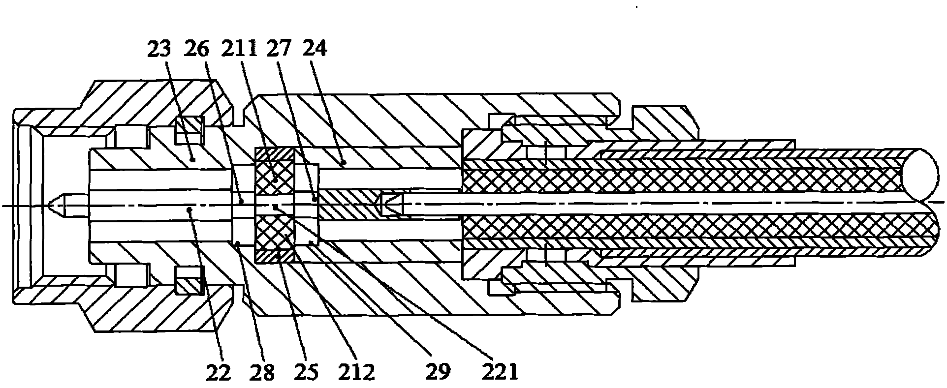
[0028] The embodiments of the present invention will be described in further detail below in conjunction with the accompanying drawings, but the present embodiments are not intended to limit the present invention, and all similar structures and similar changes of the present invention should be included in the protection scope of the present invention.

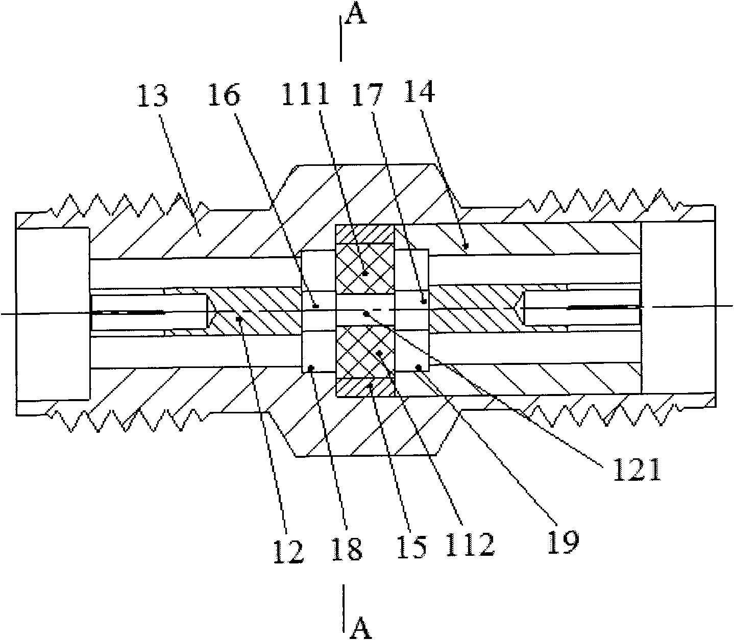
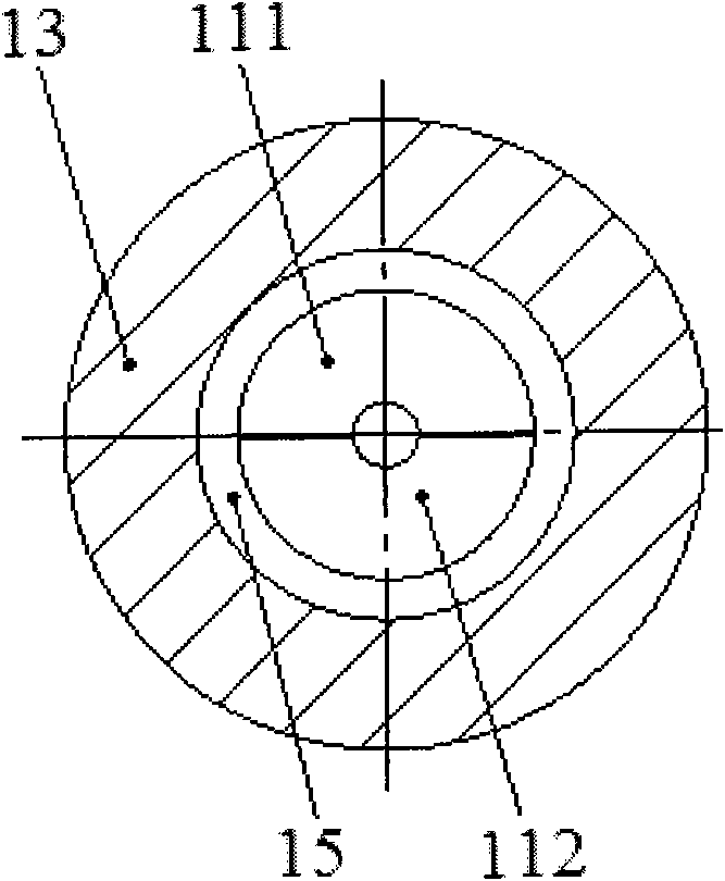
[0029] like Figure 1-Figure 2 As shown, a high-precision RF coaxial connector provided by the first embodiment of the present invention includes a support member, an outer conductor and an inner conductor 12;

[0030] The supporter includes an upper supporter 111 and a lower supporter 112, the upper supporter 111 is engaged with the lower supporter 112 in the opposite direction, and is bound by a supporter ring 15;

[0031] The outer conductor is provided with a hollow inner cavity, which is composed of a left outer conductor 13 and a right outer conductor 14, and the right end of the left outer conductor 13 is joined with th...


PUM


Abstract

The invention discloses a high-precision radio frequency coaxial connector which relates to the technical field of coaxial connectors and solves the technical problems of improving electrical characteristics and mechanical reliability, reducing processing techniques and reducing processing cost. The connector comprises a support, an outer conductor and an inner conductor, wherein the outer conductor is formed by jointing a left outer conductor and a right outer conductor; the support is arranged in the outer conductor and is located at the joint part of the left outer conductor and the right outer conductor; the inner conductor is inserted in the outer conductor and penetrates through the support; and the support is columnar, both sides of the support are respectively provided with a left inner conductor compensation tank and a right inner conductor compensation tank around the periphery of the inner conductor, a left outer conductor compensation tank is located on the inner wall of the left outer conductor, and a right outer conductor compensation tank is located on the inner wall of the right outer conductor. The connector provided by the invention has excellent electrical characteristics, high mechanical reliability, simple processing technique, low processing cost and high product qualification rate.

Description

technical field [0001] The invention relates to the technology of coaxial connectors, in particular to the technology of a high-precision radio frequency coaxial connector. Background technique [0002] RF coaxial connectors are components that connect electrical circuits, and have been widely used in RF microwave systems, microwave components, microwave equipment testing and other fields. [0003] According to the transmission line theory, in order to achieve ideal matching transmission characteristics in a wide operating frequency band, the RF coaxial connector usually needs to use an air medium at the mating interface between the connector and the connector. The ideal is that all connectors use air medium. in order to achieve the best characteristic impedance matching. However, RF coaxial connectors used in systems, connections between components, and testing fields with high precision requirements not only need to have excellent electrical characteristics in the entire ...

Claims


Application Information

Patent Timeline
Patent Type & Authority Applications(China)
IPC IPC(8): H01R9/05H01R13/02H01R13/46H01R13/502
Inventor 王云胜杜承法
Owner SHANGHAI TUYUE ELECTRONICS CO LTD
Why Eureka
Eureka Blog
Learn More