
Moving area detection method and device

A motion area, edge detection technology, applied in the field of video processing, can solve the problem of inaccurate extraction of moving object information

Active Publication Date: 2010-10-06
BEIJING ITARGE TECH CO LTD
View PDF0 Cites 5 Cited by
  • Summary
  • Abstract
  • Description
  • Claims
  • Application Information

AI Technical Summary

Problems solved by technology

[0004] Existing detection methods for video motion areas are more representative of the background difference method and the frame difference method. The background difference method is the most commonly used method, which is usually applied to a static background environment. The model is used as a reference to compare with the current frame image to detect the foreground motion information. The background difference method has certain limitations and can only be applied to a fixed and static background. It is powerless to detect moving areas in a complex and dynamic environment. The frame difference method is Based on the change between frames, the principle is to obtain the moving area of ​​the object by calculating the change between adjacent frames. This method is not accurate for the information extraction of the detected moving object, and is usually suitable for the preliminary detection of fast moving objects.

Method used


Image

  • Moving area detection method and device
  • Moving area detection method and device
  • Moving area detection method and device

Examples


Embodiment Construction

[0023] The specific implementation manners of a method and device for detecting a motion region provided in the embodiments of the present application will be described in detail below with reference to the accompanying drawings.

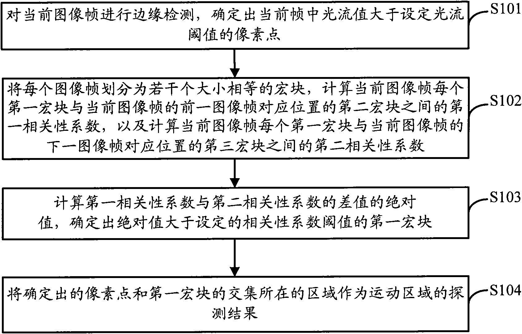
[0024] The detection method of the motion area provided by the embodiment of the present invention, such as figure 1 shown, including the following steps:

[0025] S101. Perform edge detection on the current image frame, and determine the pixel points in the current frame whose optical flow value is greater than the set optical flow threshold;

[0026] S102. Divide each image frame into several macroblocks of equal size, and calculate the first correlation between each first macroblock of the current image frame and the second macroblock at the corresponding position of the previous image frame of the current image frame coefficient, and calculate the second correlation coefficient between each first macroblock of the current image frame and the th...


PUM


Abstract

The invention provides a moving area detection method and a moving area detection device. The method comprises the following steps of: performing edge detection on a current image frame and determining pixel points, having luminous flux values greater than a preset luminous flux threshold value, in the current frame; dividing each image frame into a plurality of macro blocks with an identical size, calculating a first correlation coefficient between each first macro block of the current image frame and a second macro block at a corresponding position of the previous image frame of the current image frame, and calculating a second correlation coefficient between each macro block of the current image frame and a third macro block at the corresponding position of the next image frame of the current image frame; calculating absolute values of differences between the first correlation coefficients and the corresponding second correlation coefficients and determining the first macro blocks having the correlation coefficient difference absolute values are greater than a preset correlation coefficient threshold; and determining an area where the intersection of sets of the determined pixel points and the first macro blocks as a moving area detection result. Through the method and the device, the accurate detection of a moving area in the image frame is realized by utilizing the characteristics of the moving area and unmoving area in the image frame.

Description

technical field [0001] The present application relates to the field of video processing, and in particular to a method and device for detecting a motion region. Background technique [0002] In recent years, object movement detection technology has attracted extensive attention of many computer vision scholars, mainly because of its promising applications in many fields, especially in the field of video surveillance. [0003] Video surveillance systems are often used in unattended but high-security places such as bank vaults, etc. The characteristic of this kind of place is that, usually under safe conditions, the surveillance video is a static image that does not change or continuously changes slowly Once a fast-moving object appears in the surveillance video image, it is very likely that there is an abnormal situation in the monitored place, which triggers an alarm from the video surveillance system. The above characteristics of places with high safety requirements are mor...

Claims


Application Information

Patent Timeline
IPC IPC(8): H04N5/14G06T7/20
Inventor 杨云飞
Owner BEIJING ITARGE TECH CO LTD
Learn More