Quantitative method for embedded video coder
A technology of video encoder and quantization method, which is applied in the embedded field, can solve the problems of not considering the difference in sensitivity between low-frequency and high-frequency components, poor processing efficiency, and affecting the overall efficiency of the encoder, so as to avoid image quality degradation, The effect of improving the overall efficiency
Active Publication Date: 2010-10-06
河南金鹏信息技术股份有限公司
View PDF0 Cites 1 Cited by
- Summary
- Abstract
- Description
- Claims
- Application Information
AI Technical Summary
Problems solved by technology
Generally speaking, each set of quantization schemes in the video encoder has its certain application environment and application range, and the quantization technology in the video compression standard also has its limitations: in the H.263 quantization technology, the image transformation coefficient does not use Instead of visual quantization matrices, quantization factors are used directly for processing
In this way, although the implementation is relatively simple, the difference in the sensitivity of human vision to low-frequency and high-frequency components is not considered. Compared with the method considering visual factors, the subjective quality of the image processed by this method is slightly worse.
MPEG's quantization strategy is a relatively mature quantization technology that takes into account the characteristics of human vision, but MPEG's quantization is completed in two steps: first, the visual quantization matrix is used to process the coefficients, and then the quantization factors are used to process the coefficients twice. The two-step quantization method reduces the quantization efficiency of the encoder
At the same time, MPEG quantization processing requires a large number of division operations. In the implementation of DSP-based video encoders, since DSP does not provide corresponding hardware division components, if this quantization strategy is directly adopted, the processing efficiency will be poor.
In addition, DSP adopts the principle of pipeline operation, and a maximum of 8 instructions can work in parallel in a single cycle. However, in the standard quantization technology, due to the existence of a large number of conditional judgments and branches in the algorithm of saturation processing and misconfiguration control, DSP cannot effectively perform Parallel processing performance, which affects the overall efficiency of the encoder
Method used
View moreImage
Smart ImageViewing Examples


Examples
Embodiment Construction
Login to View More PUM
 Abstract
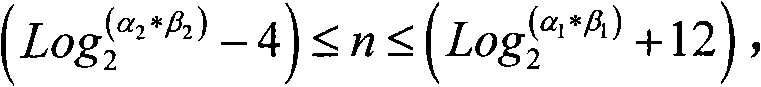
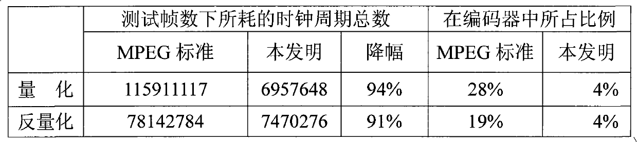
The invention discloses a quantitative method for an embedded video coder, which constructs a displacement quantization matrix to substitute shift operation for division operation, and comprises the following steps: 1), constructing the displacement quantization matrix Q1=2n+4 / (Q[ i, j ] Kq), wherein Q[ i, j ] is a vision quantization matrix, Kq is a quantization factor, and n is the number of bits of displacement; 2), setting the numeric areas of the quantization factor Kq and the vision quantization matrix Q[ i, j ], i.e. if alpha 1<= Kq <= alpha 2, and beta 1<= Q[ i, j ]<=beta 2, n is an element of Z+; and 3), carrying out quantization, wherein the quantization result is that y=32x / (2Q[ i, j ] Kq)=(2n+4x / ( Q[ i, j ] Kq))>>n, x is a coefficient to be quantized, and >> is a right shift operational character. By adopting the technical scheme, the invention utilizes the constructed displacement quantization matrix to change the division operation in the quantization process into the shift operation, thus realizing rapid one-step quantization; different quantization strategies are adopted in terms of different video coding block types, thus avoiding reduced image quality caused by unified quantization; and the MPEG-4 mismatch control algorithm suitable for a DSP is selected to be used for inverse quantization, thus effectively improving the overall efficiency of the coder.
Description
technical field The invention relates to a quantization method, in particular to a video encoder quantization method based on an embedded DSP chip. Background technique Due to the large amount of audio and video encoding calculations, the current practical system widely uses general-purpose high-performance digital signal processing chips DSP. In terms of video processing capabilities, there is still a certain gap between general-purpose DSP chips and dedicated video processing chips. To achieve the performance achieved by dedicated video processing chips, it is necessary to optimize and improve the software video compression algorithm according to the hardware characteristics of DSP chips. To make up for the lack of DSP chips in terms of processing power. H.26x and MPEG-x are currently two popular audio and video coding standards. Both of them first eliminate the redundancy in the time domain of moving images through motion estimation and motion compensation, and then use...
Claims
Login to View More Application Information
Patent Timeline
 IPC IPC(8): H04N7/26H04N7/50H04N19/124
Inventor 苏士美周兵王宗敏
Owner 河南金鹏信息技术股份有限公司
Features
- Generate Ideas
- Intellectual Property
- Life Sciences
- Materials
- Tech Scout
- Unparalleled Data Quality
- Higher Quality Content
- 60% Fewer Hallucinations
Learn More Browse by: Latest US Patents, China's latest patents, Technical Efficacy Thesaurus, Application Domain, Technology Topic, Popular Technical Reports.
© 2025 PatSnap. All rights reserved.Legal|Privacy policy|Modern Slavery Act Transparency Statement|Sitemap|About US| Contact US: help@patsnap.com