High-frequency heating apparatus, state detecting apparatus and method for detecting operating state of high-frequency heating apparatus
A state detection device and technology of operation state, applied in lighting and heating equipment, electric heating device, microwave heating and other directions, can solve the problems of increasing device cost and total number of assembly processes, and achieve the effect of preventing false detection
- Summary
- Abstract
- Description
- Claims
- Application Information
AI Technical Summary
Problems solved by technology
Method used
Image

Examples
no. 1 example
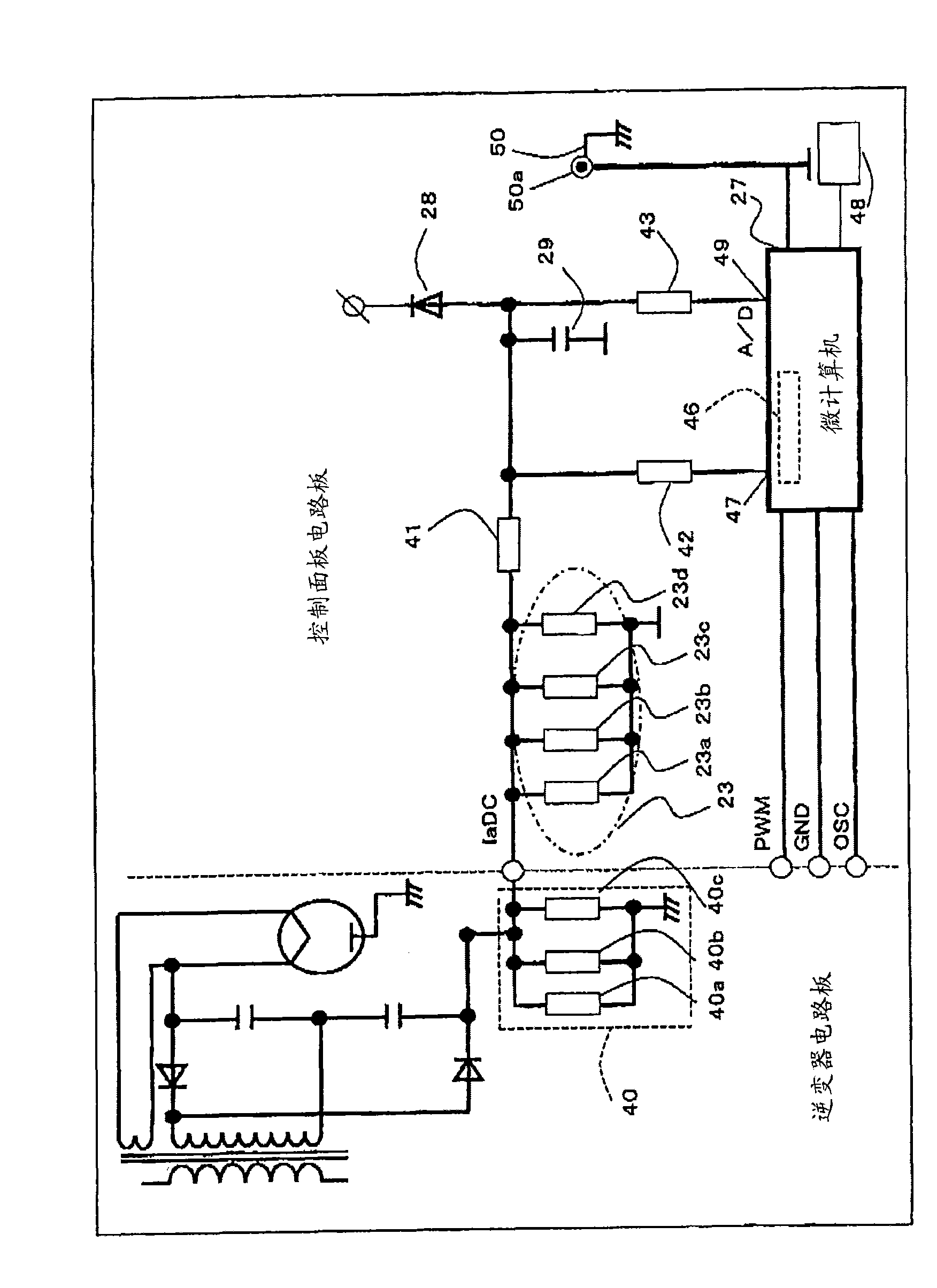
[0086] figure 1 is a diagram showing a high-frequency heating device such as a microwave oven according to an embodiment of the present invention, and specifically showing a configuration of a portion related to detection of an operating state of the high-frequency heating device. exist figure 1 In this, AC power from a commercial power supply is rectified into DC current by a rectifier circuit, then smoothed by a smoothing circuit configured on the output side of the rectifier circuit and a smoothing capacitor of a choke coil, and applied to the input side of the inverter. The DC current is converted into a desired high-frequency (20 to 40 kHz) current by the on / off operation of the semiconductor switching elements of the inverter. The inverter is driven by an inverter control circuit for controlling a semiconductor switching element that switches DC current at high speed, thereby switching the current flowing into the primary side of the step-up transformer into an on / off s...
no. 2 example
[0119] Next, a second embodiment according to the present invention will be described in detail with reference to the drawings.
[0120] Figure 4 is a diagram showing a high-frequency heating device 100 (such as a microwave oven) according to this embodiment of the present invention, and specifically showing the configuration of a portion related to the detection of the operating state of the high-frequency heating device. exist Figure 4 In this, AC power from a commercial power supply is rectified into DC current by a rectifier circuit, then smoothed by a smoothing circuit configured on the output side of the rectifier circuit and a smoothing capacitor of a choke coil, and applied to the input side of the inverter. The DC current is converted into a desired high-frequency (20 to 40 kHz) current by the on / off operation of the semiconductor switching elements of the inverter. The inverter is driven by an inverter control circuit for controlling a semiconductor switching ele...
no. 3 example
[0166] According to the second embodiment, the corresponding value of the anode current is detected during a period of one rotation of the radio wave agitating member as the rotating member. According to the present embodiment, regardless of a specific time period of one rotation of the radio wave agitating member, in the case of using (1) threshold value control or (2) change value detection control, the threshold value of (1) or (2) is controlled according to the high frequency The output of the heating device (output control signal) changes. In other words, each threshold can be changed according to an arbitrary time and an arbitrary number of detections. In this case, as in the foregoing embodiment, the foregoing three methods (A) to (C) can be used.
[0167] That is, in this embodiment, in the second embodiment refer to Image 6 with 7 Each of the illustrated calculation of the IaDC value at each segment and the detection of the rotation of the rotating antenna 68, 69 ...
PUM
 Abstract
Description
Claims
Application Information
 - Generate Ideas
- Intellectual Property
- Life Sciences
- Materials
- Tech Scout
- Unparalleled Data Quality
- Higher Quality Content
- 60% Fewer Hallucinations
Browse by: Latest US Patents, China's latest patents, Technical Efficacy Thesaurus, Application Domain, Technology Topic, Popular Technical Reports.
© 2025 PatSnap. All rights reserved.Legal|Privacy policy|Modern Slavery Act Transparency Statement|Sitemap|About US| Contact US: help@patsnap.com