
Piston used for connection rod-free reciprocating-rotating movement converting device and equipment thereof

A technology of rotary motion, conversion device, applied in the direction of piston, engine element, machine/engine, etc., to avoid the effect of piston sticking

Active Publication Date: 2012-01-04
中清能(北京)科技有限公司
View PDF3 Cites 0 Cited by
  • Summary
  • Abstract
  • Description
  • Claims
  • Application Information

AI Technical Summary

Problems solved by technology

When the reciprocating member in the middle position is a piston, the prior art adopts a structure similar to that of the pistons on both sides, so that, under the same size, it is difficult to make the quality of the piston meet the above-mentioned mass relationship; in order to increase the piston Therefore, the volume of the piston has to be increased, and correspondingly, the size of the reciprocating track on which it is located must also be increased, resulting in an increase in the volume of the cavity of the body, and a significant decrease in its stiffness and strength.

Method used


Image

  • Piston used for connection rod-free reciprocating-rotating movement converting device and equipment thereof
  • Piston used for connection rod-free reciprocating-rotating movement converting device and equipment thereof
  • Piston used for connection rod-free reciprocating-rotating movement converting device and equipment thereof

Examples


Embodiment Construction

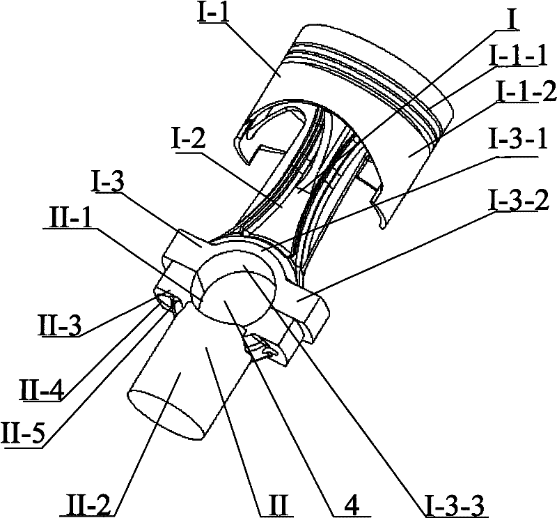
[0035] Please see figure 1 , this figure is the piston used in the internal combustion engine using the crank-slider mechanism or end shaft-moving shaft mechanism provided by the first embodiment of the present invention.

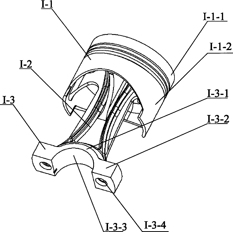
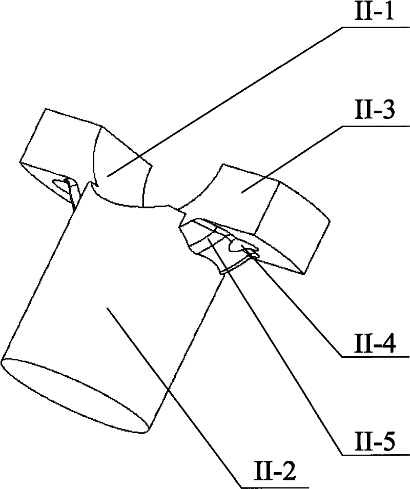
[0036] figure 1 The piston is shown as a single-acting piston with one piston head. From the longitudinal direction, the piston includes a piston head I and an auxiliary guide part II. In this embodiment, these two parts are made separately, from figure 1 It can be seen from the figure that the ears on both sides of the upper end of the auxiliary guide part II are respectively provided with positioning threaded holes, and the corresponding positioning threaded holes are also provided on the piston head I; through this positioning connection structure, the above-mentioned piston head can be Part I and auxiliary guide part II are fixed as one. figure 2 It is a perspective view of the above-mentioned piston head 1, image 3 It is a perspective view of...


PUM


Abstract

The invention provides a piston used for a connection rod-free reciprocating-rotating movement converting device. The piston is a single-action piston; the other end opposite to the head of the piston is provided with an auxiliary guide part. The piston head is composed of a top part, a support part and a bottom part. The top part includes a crown part and a shirt part. The support part is connected between the crown part bottom surface and the bottom part. The bottom part has a first arc opening which opens downward. The top part of the auxiliary guide part has a second arc opening which opens upward. The first arc opening and the second arc opening are opposite to form an integrate hole. The periphery surface of the skirt part is matched with an inner wall surface of a cylinder, and the gap is less than that between the crown part and the cylinder in which a gas ring and an oil ring are added on the crown part. The periphery surface of the auxiliary guide part is matched with an auxiliary runway of a machine body, and a fit gap between the auxiliary guide part and the auxiliary runway is less than that between the crown, after being provided with an oil ring and a gas ring, of the piston and the inner wall of the cylinder. The adoption of the above piston can effectively reduce the friction loss of reciprocating movement. The invention can simultaneously provide an internal-combustion engine and a compressor using the above piston.

Description

technical field [0001] The invention relates to a piston, in particular to a piston for a connecting-rod-free reciprocating-rotational conversion device; the invention also provides an internal combustion engine and a compressor using the piston. Background technique [0002] The common feature of the internal combustion engine adopting the crank circular slider structure or the end shaft-moving shaft device is that no connecting rod is provided. The non-connecting rod reciprocating-rotary motion conversion mechanism mentioned in the present invention specifically refers to the above two forms, Of course, new forms arising with technological development are not excluded. [0003] The above-mentioned non-connecting rod structure can overcome the defects of the traditional crank connecting rod structure internal combustion engine or compressor. The "crank circular slider reciprocating piston internal combustion engine" provided by Chinese patent document CN85100358B, the "cr...

Claims


Application Information

Patent Timeline
Patent Type & Authority Patents(China)
IPC IPC(8): F02F3/00F02B75/32F04B39/00
Inventor 黎明黎正中
Owner 中清能(北京)科技有限公司
Learn More