LTCC lamination double-fed circularly polarized micro-strip paster antenna

A technology of microstrip patch antenna and circular polarization, which is applied in the direction of antenna, antenna grounding device, radiating element structure, etc. It can solve the problem of high precision of chip cutting angle and poor circular polarization effect of the antenna. Problems such as high antenna axial ratio parameters, to achieve the effect of improving stability and reliability, expanding bandwidth, and improving gain

A technology of microstrip patch antenna and circular polarization, which is applied in the direction of antenna, antenna grounding device, radiating element structure, etc. It can solve the problem of high precision of chip cutting angle and poor circular polarization effect of the antenna. Problems such as high antenna axial ratio parameters, to achieve the effect of improving stability and reliability, expanding bandwidth, and improving gain

CN101859927AInactive Publication Date: 2010-10-13UNIV OF ELECTRONICS SCI & TECH OF CHINA

Image

  • LTCC lamination double-fed circularly polarized micro-strip paster antenna
  • LTCC lamination double-fed circularly polarized micro-strip paster antenna
  • LTCC lamination double-fed circularly polarized micro-strip paster antenna

Examples


Embodiment approach

[0025] The present invention will be described in further detail below with reference to the accompanying drawings and an embodiment, but the embodiment of the present invention is not limited thereto.

[0026] like Image 6 As shown, the center frequency point of the microstrip patch antenna provided by the embodiment of the present invention is 1.268GHz, which is a BD-2 type microstrip receiving patch antenna. The present invention can achieve an impedance bandwidth exceeding 40MHz within a section thickness of 3mm. Microstrip patch antenna, and the axial ratio of the antenna can be less than 1.5.

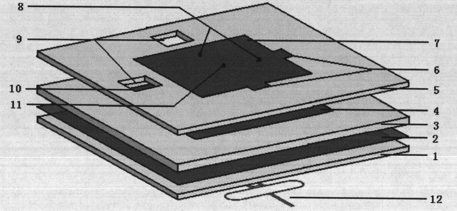
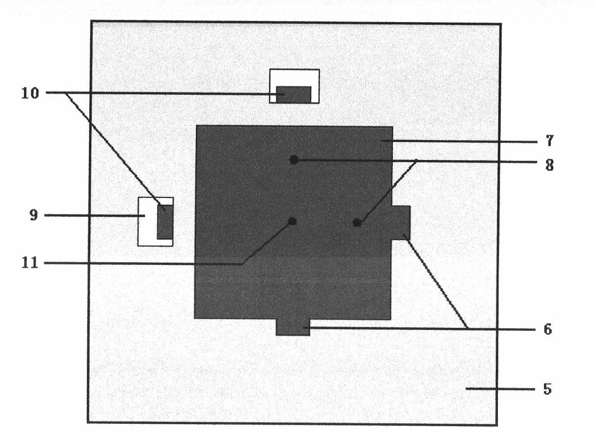
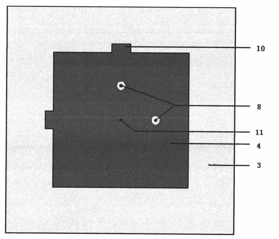
[0027] as shown in the picture Figure 1 to Figure 5 As shown, a kind of LTCC laminated double-fed circularly polarized microstrip patch antenna provided by the present invention comprises:

[0028] Lower dielectric substrate 1: the substrate is formed by stacking five LTCC cast film sheets with a thickness of 0.1 mm and a dielectric constant of 14. The lower surface of the sub...


PUM


Abstract

The invention relates to an LTCC lamination double-fed circularly polarized micro-strip paster antenna, which belongs to the technical field of antennae and particularly relates to a micro-strip paster antenna with a low section. The antenna comprises two layers of radiation metal pasters, a grounding metal layer and a feed layer, wherein the four functional layers are spaced by three layers of medium LTCC ceramic dielectric substrates, and the feed layer consists of a Wilkins-layer power divider and a 90-degree phase shift micro-strip line. The geometric centers of the two layers of radiation metal pasters and the grounding metal layer are connected with each other by metal grounding pins, and the double-fed points with 90-degree phase difference on the feed layer are connected with the upper layer of radiation metal paster via metal feed pins. Two edges of each of the two layers of radiation metal pasters are respectively provided with two rectangular frequency modulation electrodes. The invention not only can better give consideration to the performance requirements of low section, broadband and circular polarization of the micro-strip antenna, but also can appropriately regulate the frequency band of the antenna conveniently.

Description

technical field [0001] The invention belongs to the technical field of antennas, and in particular relates to a low-profile microstrip patch antenna. Background technique [0002] Microstrip patch antenna has many advantages such as small size, light weight, thin profile, easy conformal, etc. It is widely used in satellite positioning, wireless communication, remote sensing, aerospace and other fields. In airborne or missile-borne applications, the performance requirements of microstrip patch antennas are particularly emphasized for their low profile, wide frequency band and circular polarization. However, the input impedance of the microstrip patch antenna is very sensitive to changes with frequency, resulting in a narrow impedance bandwidth. The current microstrip patch antennas generally use organic dielectric materials or ceramic materials as substrates. In order to expand the bandwidth of microstrip patch antennas, common methods include increasing the thickness of the...

Claims


Application Information

Patent Timeline
13 Oct 2010
Publication
CN101859927A
IPC
H01Q13/08; H01Q1/38; H01Q1/48; H01Q3/34
Inventors
苏摦; εΌ ζ€€ζ­¦