Single-phase and three-phase double voltage-boosting and reducing power factor correcting circuit and control method thereof

A power factor correction, buck-boost technology, applied in the output power conversion device, the conversion of AC power input to DC power output, the conversion of irreversible AC power input to DC power output, etc., can solve the problem of large on-state loss and so on

Active Publication Date: 2010-10-13
DELTA ELECTRONICS INC +1
View PDF0 Cites 12 Cited by
  • Summary
  • Abstract
  • Description
  • Claims
  • Application Information

AI Technical Summary

Problems solved by technology

[0012] The main purpose of this case is to provide a single-phase / three-phase dual-boost buck-boost power factor correction circuit and its control method, which can solve the problems of the boost diode in the traditional single-phase three-potential buck-boost power factor correction circuit. For the problem of excessive on-state loss, the three-phase dual buck-boost power factor correction circuit is composed of three independent single-phase double buck-boost power factor correction circuits. Since there is a neutral line, the first and second The second and the third single-phase double buck-boost power factor correction circuits do not affect each other and operate independently of each other; they can be used to improve the total harmonic distortion and improve the efficiency of the three-phase buck-boost power factor correction circuit, so the present invention The provided three-phase buck-boost power factor correction circuit has relatively high efficiency and improves the power density of the system; it also has the advantages of separate control of each phase current and easy realization of a parallel system.

Method used


Image

  • Single-phase and three-phase double voltage-boosting and reducing power factor correcting circuit and control method thereof
  • Single-phase and three-phase double voltage-boosting and reducing power factor correcting circuit and control method thereof
  • Single-phase and three-phase double voltage-boosting and reducing power factor correcting circuit and control method thereof

Examples


Embodiment Construction

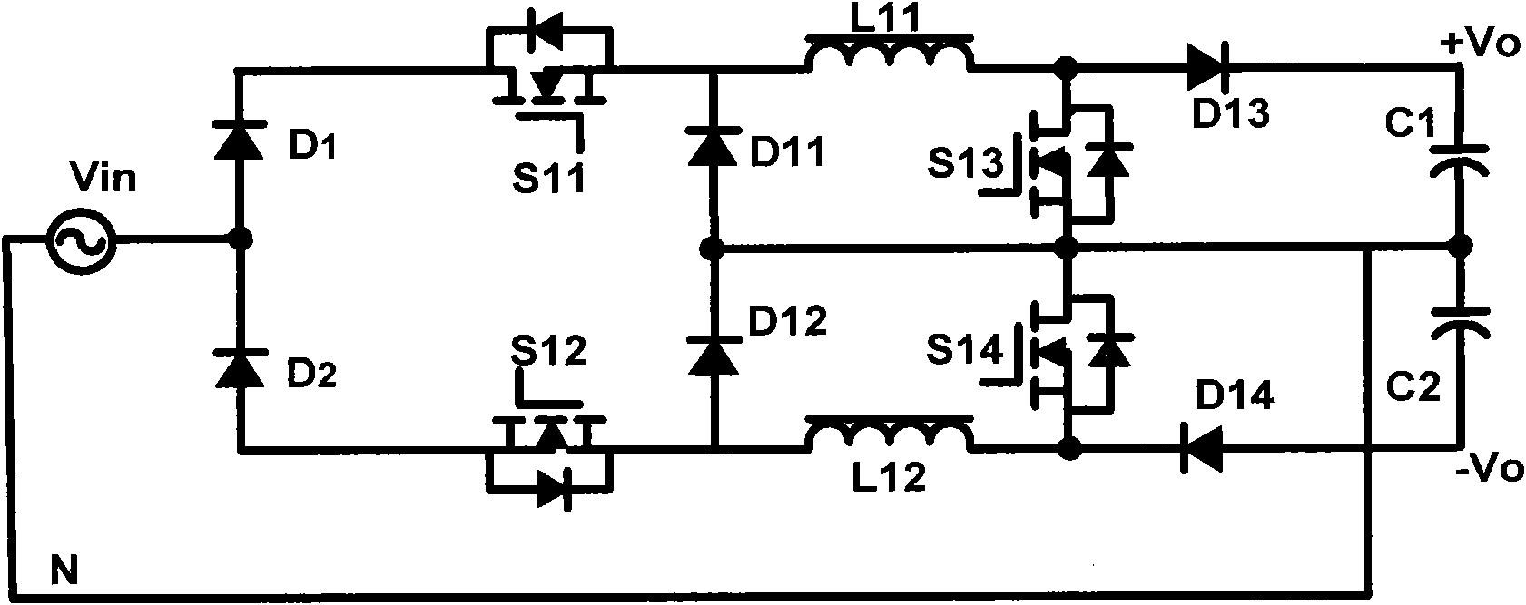
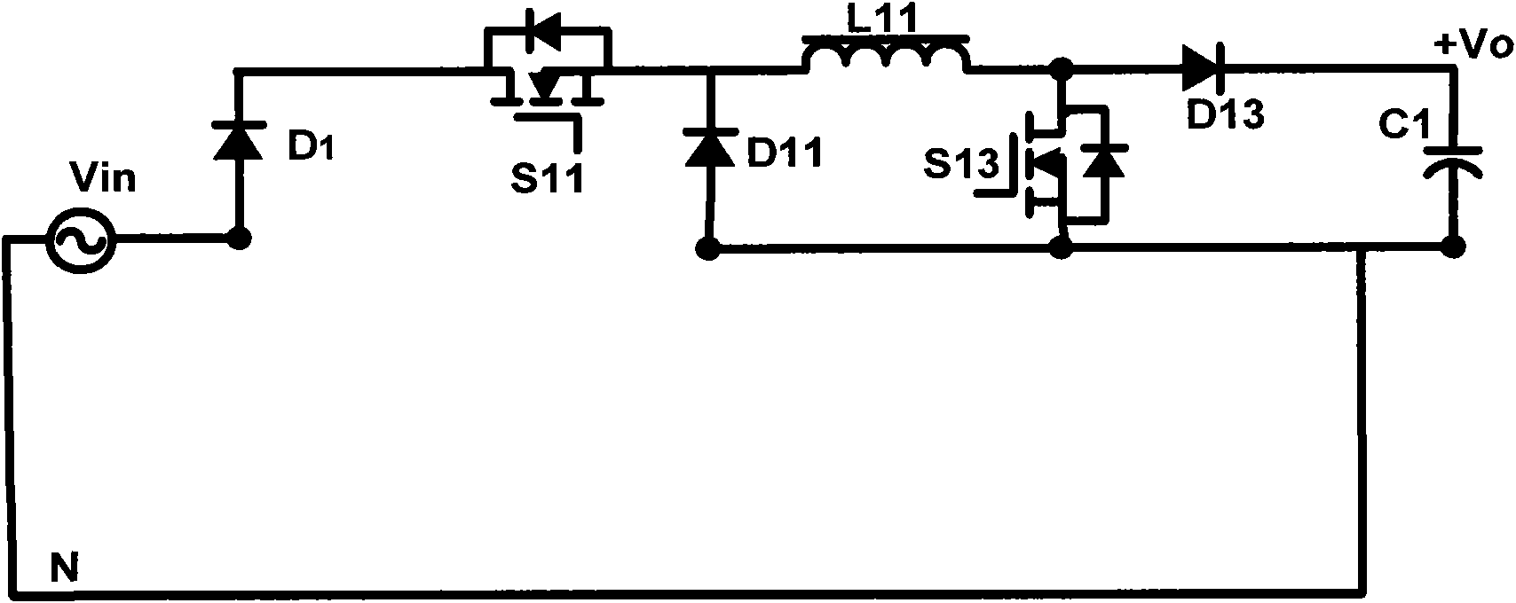
[0040] In order to overcome the shortcoming of the traditional buck-boost PFC (buck-boost PFC) circuit, the present invention proposes a dual buck-boost / buck PFC circuit with an improved topology, such as Figure 4 shown. Figure 4 The circuit in can be regarded as composed of two parts, the upper part of which is the aforementioned buck-boost PFC circuit, and the lower part is the buck circuit. see Figure 4 , which has diodes Di, diodes Dj1-Dj2, diodes D13-D14, switches Sj1-Sj2, switches S13-S14, inductors Lj1-Lj2 (where i=1-4, j=1-2), capacitors C1-C2 and A neutral line N connects the neutral point of the power supply to the neutral point of the PFC circuit, and the neutral point of the PFC circuit is the connection node of the capacitors C1-C2. The improved dual buck-boost / buck circuit uses the method of input current partition control in buck and boost modes to greatly reduce the on-state loss of the boost diode D13 in the circuit. In practical applications, components ...


PUM


Abstract

The invention discloses a single-phase double voltage-boosting and reducing power factor correcting circuit which comprises a single-phase three-potential voltage-boosting and reducing power factor correcting circuit, a single-phase three-potential voltage-reducing power factor correcting circuit, a first output capacitor, a second output capacitor and a midline, wherein the single-phase three-potential voltage-boosting and reducing power factor correcting circuit is used for receiving an input voltage, is provided with a first output end, a middle point and a second output end and is used for outputting a first output voltage and a second output voltage; the single-phase three-potential voltage-reducing power factor correcting circuit is used for receiving the input voltage and is coupled to the first output end, the middle point and the second output end; the first output capacitor is coupled to the first output end and the middle point; the second output capacitor is coupled to themiddle point and the second output end; and the midline is coupled to the middle point. The single-phase/three-phase double voltage-boosting and reducing power factor correcting circuit and the control method thereof solve the problem of overlarge conduction loss in a voltage-reducing working mode of a voltage-boosting diode in a traditional single-phase three-potential voltage-boosting and reducing power factor correcting circuit.

Description

technical field [0001] The invention relates to a single-phase / three-phase dual buck-boost / buck PFC circuit (single-phase / three-phase dual buck-boost / buck PFC circuit) and its control method, in particular to a single-phase three-potential Single-phase three-level buck-boost PFC circuit (single-phase three-level buck-boost PFC circuit) and single-phase three-level buck PFC circuit (single-phase three-level buck PFC circuit) Step-down power factor correction circuit and its control method. Background technique [0002] Power electronics technology has developed rapidly in the past two decades and has been widely used in electric power, chemical industry, communication and other fields. Most power electronic devices are connected to the power grid through a rectifier. A typical rectifier is a nonlinear circuit composed of diodes or thyristors, which will cause serious harmonic pollution and reactive power to the grid during operation. Therefore, Become an electrical hazard. ...

Claims


Application Information

Patent Timeline
Patent Type & Authority Applications(China)
IPC IPC(8): H02M1/42H02M7/02H02M7/155
CPCY02B70/126Y02B70/10Y02P80/10
Inventor 谭惊涛周志健杨剑平苟文辉应建平
Owner DELTA ELECTRONICS INC
Why Eureka
Try Eureka