Centrifugal high-gradient magnetic method

A magnetic separation method and high gradient technology, applied in the fields of magnetic separation, solid separation, chemical instruments and methods, etc., can solve the problems of reduced concentrate quality, difficult to meet the requirements of mineral processing industry production, and small processing capacity.

Inactive Publication Date: 2010-10-20
KUNMING UNIV OF SCI & TECH
View PDF5 Cites 22 Cited by
  • Summary
  • Abstract
  • Description
  • Claims
  • Application Information

AI Technical Summary

Problems solved by technology

However, in the process of high-gradient magnetic separation, the fine-grained weak magnetic ore is easy to form magnetic agglomeration due to the strong magnetic force, resulting in the inclusion of a large number of poor intergrowths and gangues in the magnetic concentrate, which significantly reduces the quality of the concentrate; therefore, the high-gradient magnetic separation method It is suitable for roughing fine-grained weak magnetic ore to produce low-quality magnetic concentrate, and usually cannot directly produce high-quality magnetic concentrate
Centrifugal separation is very effective in selecting certain fine-grained weak magnetic minerals such as hematite, and high-quality concentrates can be obtained, but existing centrifuges cannot handle minerals with heavy mineral content and high concentrate yield, such as Knelson centrifuges etc.; or the processing capacity is very small, such as various single-wall centrifuges, which are difficult to meet the requirements of the mineral processing industry.

Method used


Image

  • Centrifugal high-gradient magnetic method
  • Centrifugal high-gradient magnetic method
  • Centrifugal high-gradient magnetic method

Examples


Embodiment Construction

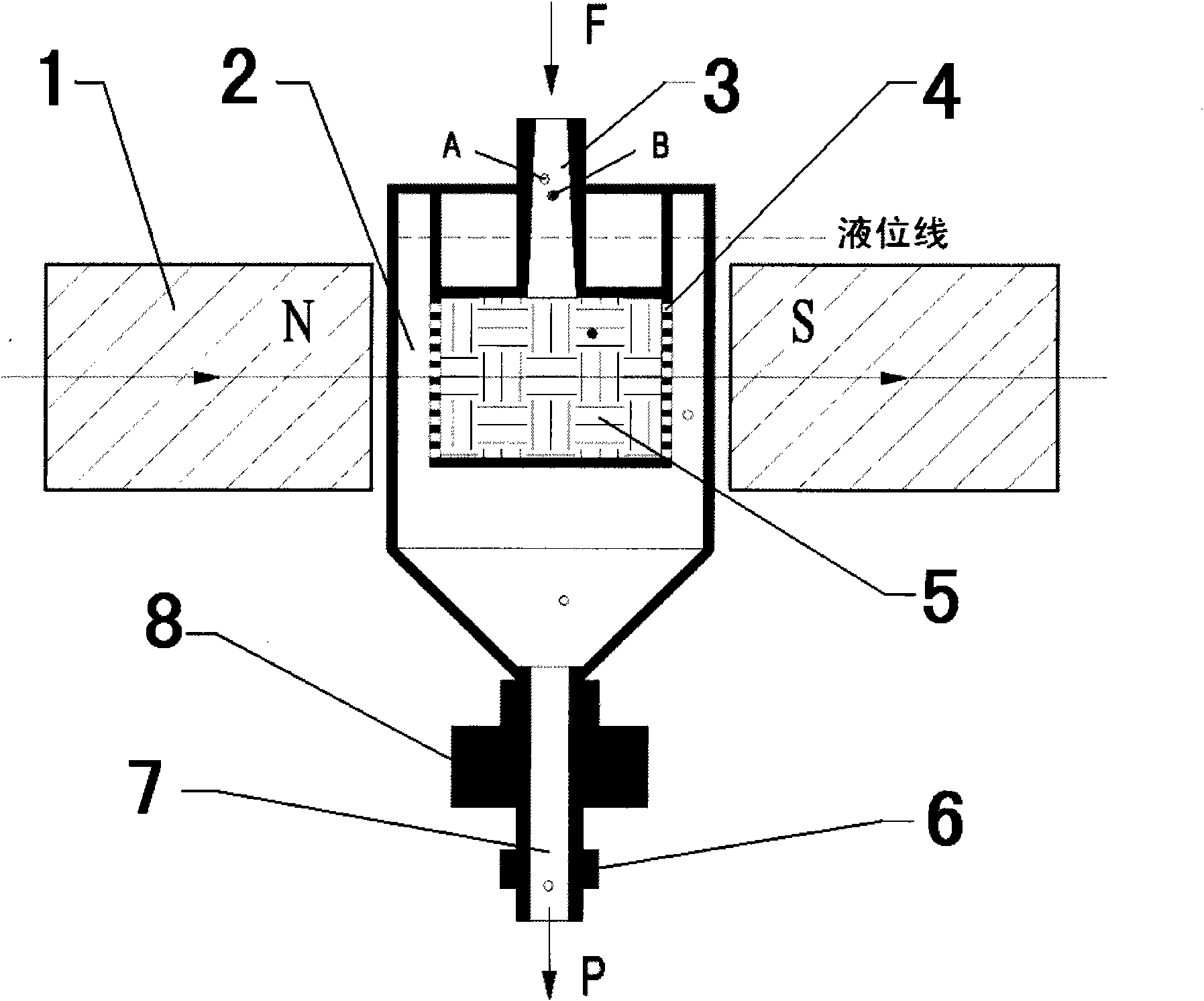
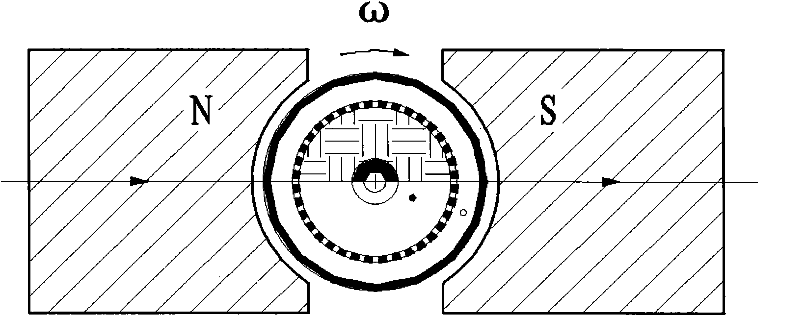
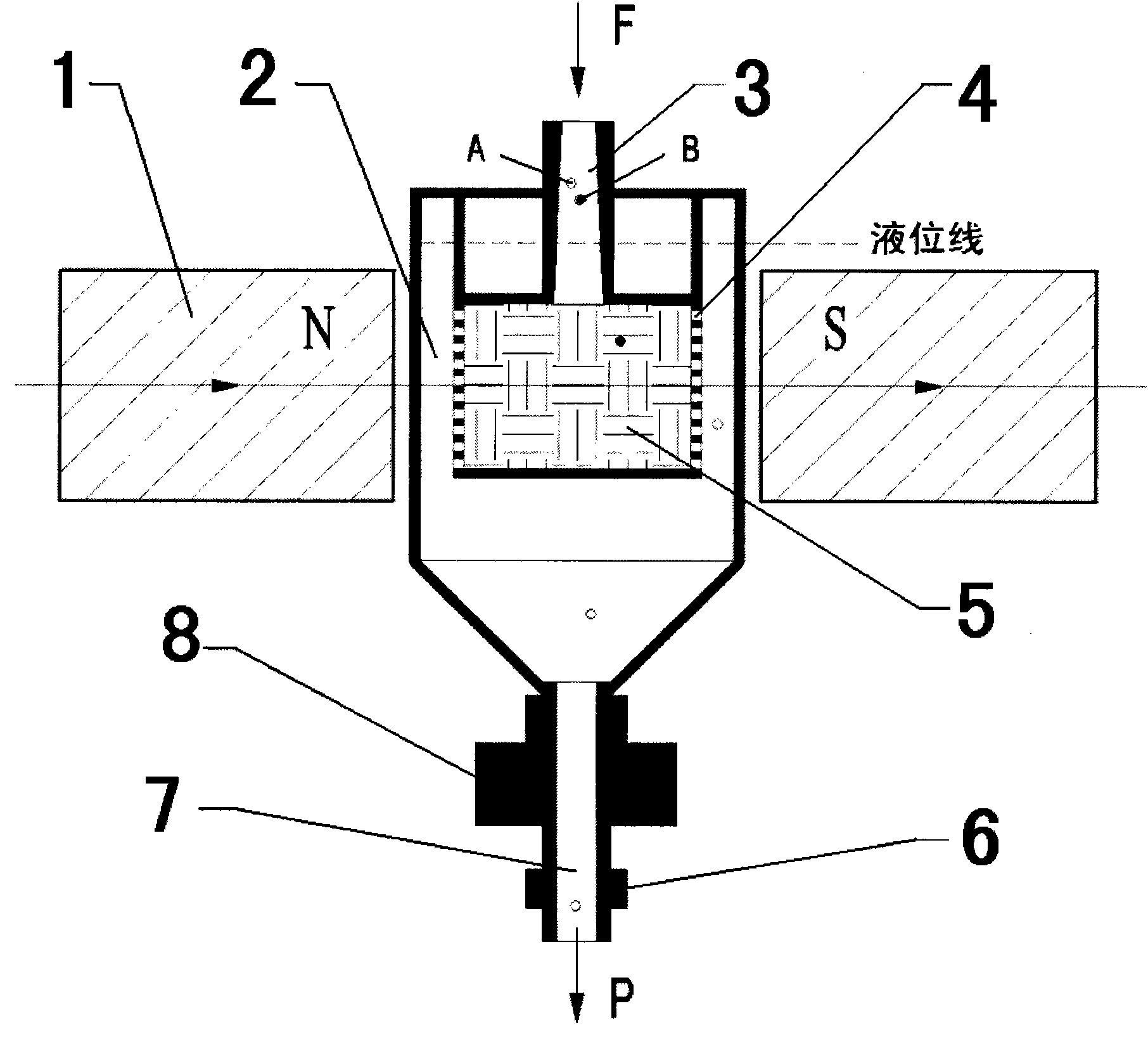
[0013] like figure 1 and 2 As shown, the ore pulp self-supply cone pipe 3 enters the sorting cylinder 2 and the magnetic medium cylinder 4, and there are holes on the cylinder wall of the magnetic medium cylinder 4 to communicate with the inner cavity of the sorting cylinder 2; The mine valve 6 keeps the ore pulp at a certain liquid level in the sorting cylinder 2 and the magnetic medium cylinder 4 . The transmission device 8 drives the entire sorting device (including the sorting cylinder 2, the magnetic medium cylinder 4, the magnetic medium 5 and the ore discharge valve 6, etc.) The high gradient magnetic field generated on the surface of the medium 5 forms a new comprehensive force field. The rotation axis of the sorting drum 2 is perpendicular to the magnetic field of the magnetic system 1 . The ore particles in the magnetic medium 5 are sorted under the comprehensive action of the high gradient magnetic field and the centrifugal force field. The magnetic force receive...


PUM


Abstract

The invention provides a centrifugal high-gradient magnetic method, which comprises the following steps: a magnetic medium cylinder with magnetic medium is fixed in the middle of a separating cylinder and rotates along with the separating cylinder in magnetic field to form a comprehensive force-field by the competition of high-gradient magnetic field and centrifugal force filed in the magnetic medium. A pulp self-feeding ore taper pipe enters into the magnetic medium cylinder to carry out separation; because magnetic force of magnetic minerals is greater than the centrifugal force, the magnetic medium can capture the magnetic minerals; because the magnetic force of poor intergrowth and gangue is less than the centrifugal force, the poor intergrowth and gangue can pass through the magnetic medium, flow out of a through-hole on a magnetic medium cylinder wall, enter into the separating cylinder and finally flow out of an ore discharging pipe at the bottom. When the magnetic minerals of captured by the magnetic medium is in saturation state, ore-feeding is ceased, the magnetic field is cut and clean water is injected, so that the magnetic minerals are washed out under the action of centrifugal force; the obtained magnetic minerals enter into the separating cylinder and then flow out of the ore-discharging pipe. The method can separate the poor intergrowth and the gangues, can be used for separating various weakly magnetic minerals, in particular being applied to producing high-quality magnetic concentrates from selected fine weakly magnetic ores, is capable of separating fine medium magnetic minerals and has stronger adaptability.

Description

technical field [0001] The invention relates to a high-gradient magnetic separation method for fine-grained weakly magnetic ores in a centrifugal force field, which can effectively separate fine-grained weakly magnetic minerals, and is especially suitable for producing high-quality magnetic concentrates by selecting fine-grained weakly magnetic ores. Background technique [0002] At present, high-gradient magnetic separation methods such as pulsating high-gradient magnetic separation technology are one of the effective methods for separating fine-grained weak magnetic minerals such as hematite, ilmenite, wolframite, and manganese ore, and are widely used. However, in the process of high-gradient magnetic separation, the fine-grained weak magnetic ore is easy to form magnetic agglomeration due to the strong magnetic force, resulting in the inclusion of a large number of poor intergrowths and gangues in the magnetic concentrate, which significantly reduces the quality of the co...

Claims


Application Information

Patent Timeline
Patent Type & Authority Applications(China)
IPC IPC(8): B03C1/247
Inventor 陈禄政
Owner KUNMING UNIV OF SCI & TECH
Why Eureka
Try Eureka