

Cutting equipment and cutting method for cutting prepregs
A cutting equipment and prepreg technology, which is applied in metal processing and other directions, can solve the problems of cutting tool edge passivation, etc., achieve high cutting size accuracy, improve health, and eliminate broken fine semi-cured resin and resin glass fiber dust. Effect
- Summary
- Abstract
- Description
- Claims
- Application Information
AI Technical Summary
Problems solved by technology
Method used
Image

Examples
Embodiment Construction
[0041] The present invention will be described in further detail below in conjunction with the accompanying drawings and specific embodiments.
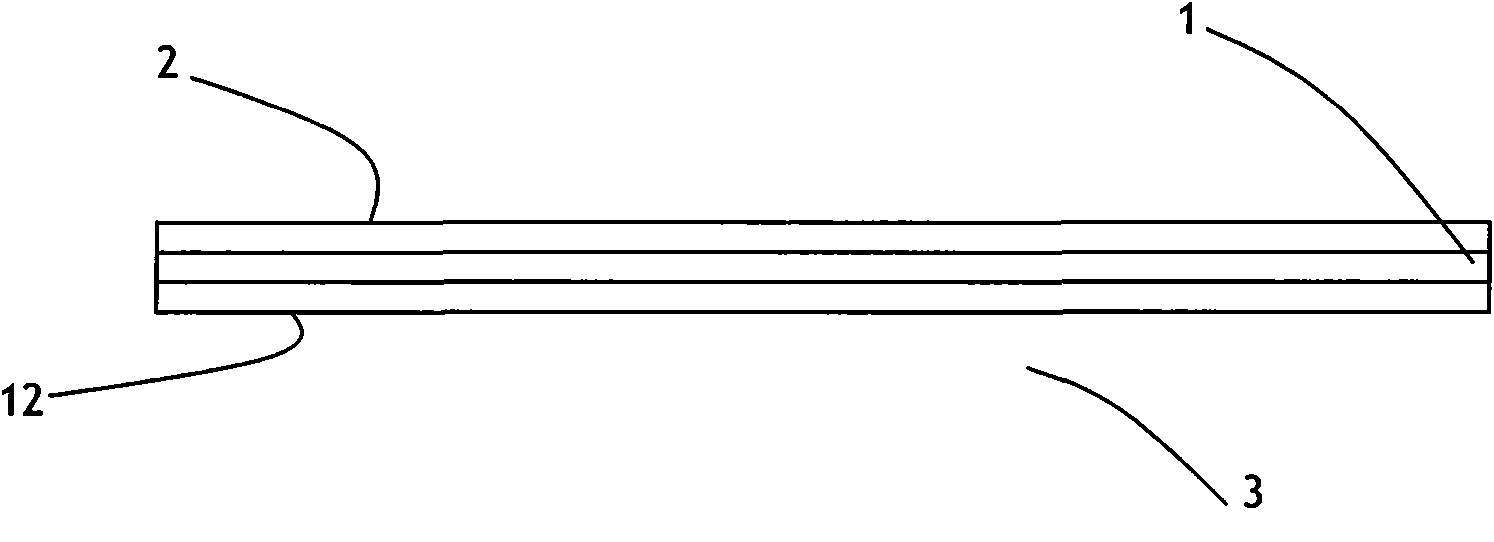
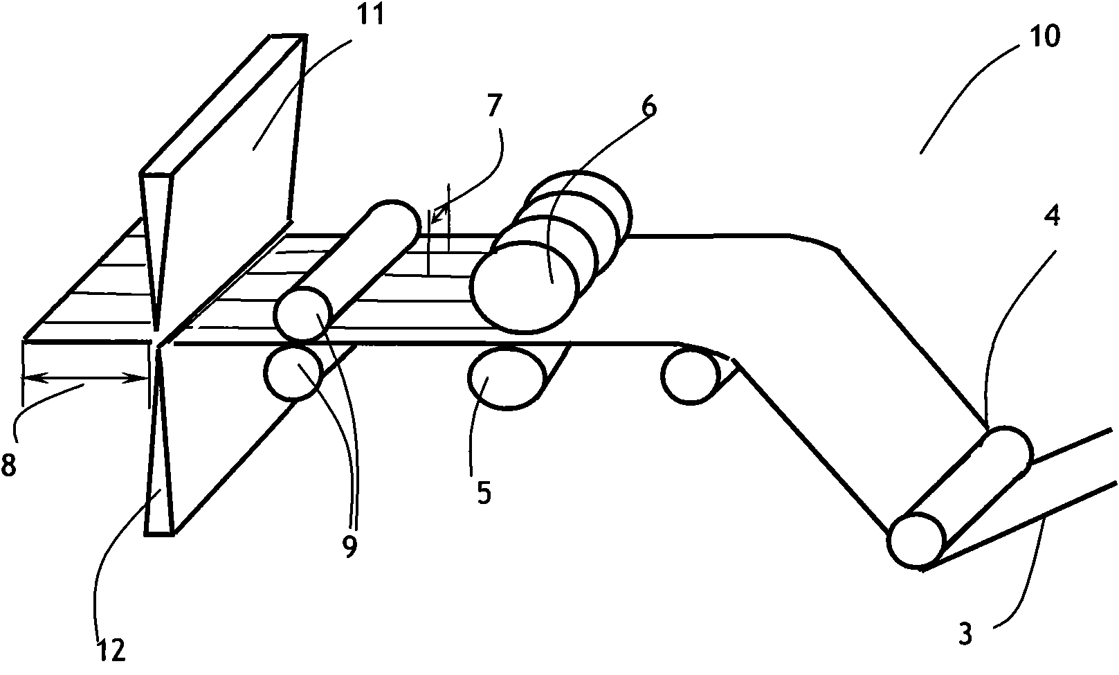
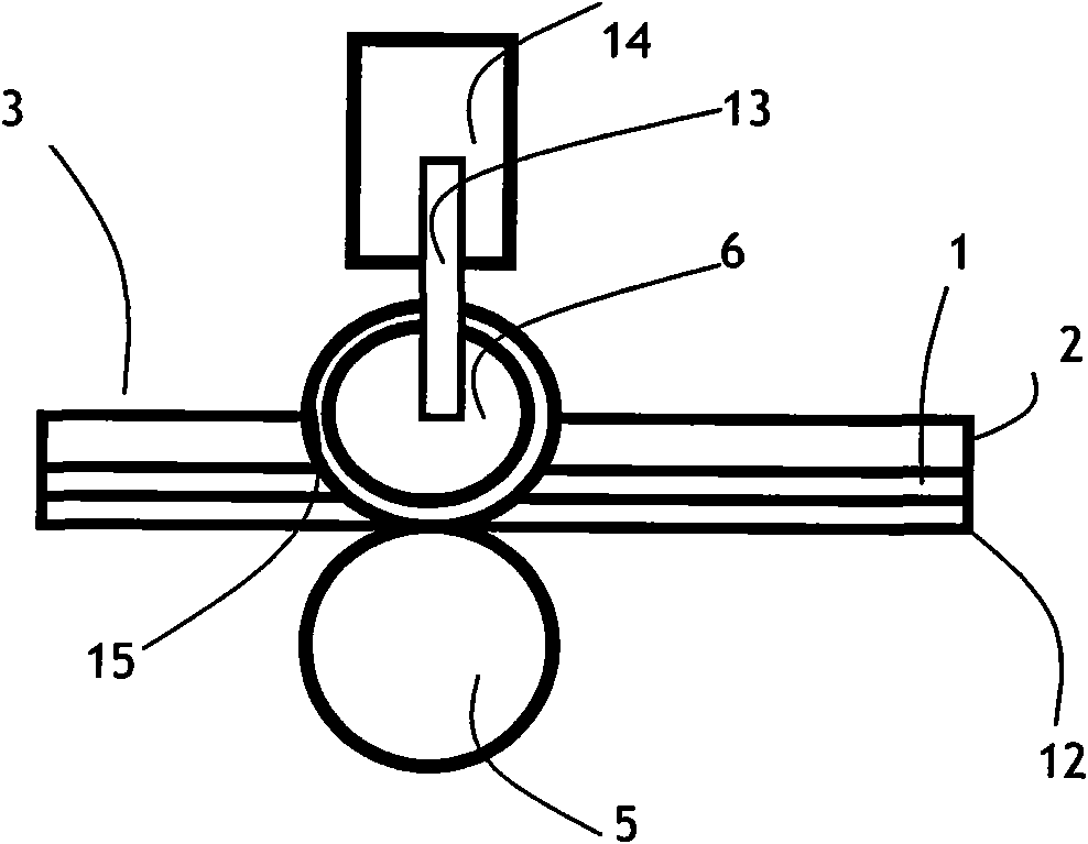
[0042] The method of round knife blade of the present invention is not curled and passivated in the process of cutting and slitting is as follows: Figure 4 As shown in the longitudinal sectional view, in the process of cutting and slitting, always keep the wheel knife blade piercing the epoxy resin 2 and glass cloth base 1 of the prepreg 3 that is in contact with the wheel knife blade 15, only piercing The epoxy resin 12 that does not pierce the semi-curing agent that is in contact with the roller, so that the blade 15 of the wheel cutter does not contact the roller during the cutting and slitting process, thereby ensuring that the blade 15 of the wheel cutter will not curl Passivation, keeping sharp while taking advantage of the brittle nature of the prepreg epoxy, after the prepreg epoxy 2 and glass cloth base 1 are cut and the pre...
PUM
 Abstract
Description
Claims
Application Information