Barrier-free folding chain elevating platform

A technology of folding and lifting platform, which is applied in the field of lifting platform, can solve the problems of inconvenient maintenance, unreasonable design and high cost, and achieve the effect of saving space, simple structure and low cost

Active Publication Date: 2010-10-20
JIANGSU CRRC ENVIRONMENT CO LTD
View PDF10 Cites 16 Cited by
  • Summary
  • Abstract
  • Description
  • Claims
  • Application Information

AI Technical Summary

Problems solved by technology

[0005] Its shortcomings are: 1. This lifting mechanism is not easy to install, and it is only suitable for fixed cooperation with fixed buildings, so it is difficult to install; 2. This lifting mechanism uses a synchronous motor to output power. The lifting arm drives the steps to move up and down relative to the guide groove, the structure is complex, the cost is too high, there is no alarm and no protection when a fault occurs, and it is inconvenient to maintain; 3. There is no protective measure for the wheelchair when lifting, and it is easy to misuse. When there is a fault or the wrong button is pressed (for example, when passengers take the elevator up, if one synchronous motor fails and the other operates normally, the platform gradually stretches into a ladder shape, and the wheelchair is equivalent to being placed on a ladder with steps. This is undoubtedly very dangerous) cannot guarantee the personal safety of passengers; 4. It covers a large area and cannot be folded, so it is not easy to move or transport as a whole after installation
5. The power output mechanism is complicated. The power output of the synchronous motor is output to the screw, threaded button, push-pull arm, lifting arm, dovetail groove, and steps to complete the action. The loss in the kinetic energy transmission process is large, and it is not suitable for energy-saving industries.
[0007] Its disadvantages are: 1. The operating mechanism is cumbersome and complicated. There are too many power sources, such as sliding motors, locking motors, tailgate motors, hydraulic systems and oil cylinders for driving up and down, and the probability of failure is high.
2. The wheelchair locking device needs to be manually hung on the hook, removed from the hook, and pressed the locking button, which increases the difficulty of operation
3. Too many limit switches and proximity switches will increase the instability of the system, that is, if one switch fails, the system may be paralyzed
4. The sliding mechanism of the platform cannot be folded, occupies a large area, has strict requirements on the vehicle type and internal space, and is not suitable for wide application
5. The hydraulic system is used as the lifting power of the wheelchair. The hydraulic system loses too much during the kinetic energy transmission process, which greatly increases the power output load of the vehicle.
At the same time, the operation of power output devices such as sliding motors, locking motors, and tailgate motors will also bring a lot of burden to the power output of the car.
That is, the overall energy consumption of the lifting mechanism is too large, and a high-power engine or vehicle power supply needs to be configured
6. The hydraulic system, sliding motor, locking motor, tailgate motor and other power devices in this lifting mechanism also greatly increase the cost and are not suitable for large-scale promotion
7. This lifting mechanism must be used in conjunction with a specific vehicle model. The installation process is complicated and requires professional modification, which has great limitations in use.
8. The function of this lifting mechanism is limited to pulling passengers who use wheelchairs, and the function is single
9. The force arm at one end of the oil cylinder is too small during the lifting process of the parallelogram lifting mechanism, which requires a large load on the oil cylinder and the design is unreasonable
This structure has high requirements on the strength of related parts, and the joints wear too fast

Method used


Image

  • Barrier-free folding chain elevating platform
  • Barrier-free folding chain elevating platform
  • Barrier-free folding chain elevating platform

Examples


Embodiment Construction

[0037] The present invention will be further described below in conjunction with the accompanying drawings and embodiments.

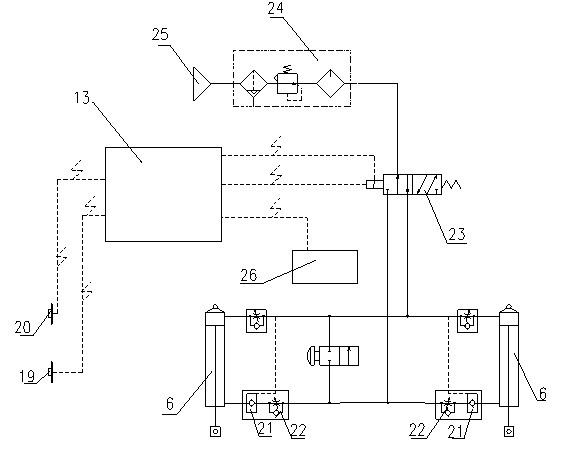
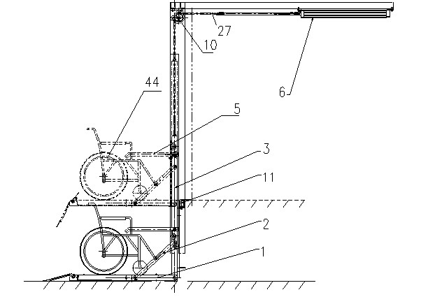
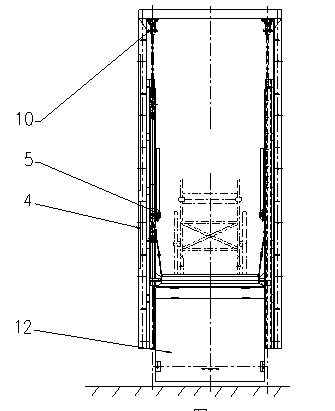
[0038] like Figure 1-15 As shown, a barrier-free folding chain lifting platform includes a door frame guide rail 4 fixed to the end surface of the corresponding wall of the vehicle or building. The door frame guide rail 4 is provided with a pull rod 3 that moves up and down along it, and the upper end of the pull rod 3 is connected to the lifting mechanism. , the lower end of the pull rod 3 is connected with the foldable pedal device, the pull rod 3 is provided with a foldable handrail device, and the lifting mechanism is connected with the electric control mechanism 13. Cylinder 6 in the lifting mechanism of the present invention is fixed on the ceiling where the rising height is, and other devices are all arranged on the door frame guide rail 4, and the door frame guide rail 4 is fixed to the vehicle or the corresponding wall end face of the building...


PUM


Abstract

The invention relates to a barrier-free folding chain elevating platform. The barrier-free folding chain elevating platform comprises a doorframe guide rail fixed to a vehicle or the end face of a corresponding wall of a building, wherein the doorframe guide rail is provided with a pull rod which can move up and down along the doorframe guide rail; the upper end of the pull rod is connected with a lifting mechanism, while the lower end is connected with a foldable pedal device; the pull rod is provided with a foldable handrail device; and the lifting mechanism is connected with an electric control mechanism. The invention solves the problem of large occupied area and also brings convenience to the transportation. A double-insurance facility for folding and positioning the pedal and limiting a folding protection plate on the elevating platform effectively ensures the safety of the elevating platform in the transportation process. The pedal is provided with a turning plate and a ribbed plate to prevent a wheel chair from sliding forwards or backwards, and the two sides are provided with foldable handrails for grabbing so as to ensure the safety of a passenger when the passenger takes the elevating platform. The pedal can be lifted for a great height by a chain wheel driven by a cylinder. By using pneumatic drive, the elevating platform has the characteristics of low manufacturing cost, simple structure, environment friendliness and no pollution.

Description

technical field [0001] The invention relates to a lifting platform, in particular to a barrier-free folding chain lifting platform. Background technique [0002] At present, most barrier-free lifting mechanisms on the market are not foldable and occupy a large area. The lifting mechanism also mostly uses a hydraulic station as power, and the cost is relatively high. At the same time, the protective measures of the lifting mechanism are not in place, and there are potential safety hazards. [0003] The Chinese patent with the notification number CN101353128A and the name "Barrier-free Elevator and Lifting Method" discloses the following technology: it consists of two or more steps connected to each other to form a step ladder, and the two sides of the lower part of each step in the step step are The shafts are respectively connected with the shaft holes on the side of the guide sleeve. The guide sleeve is sleeved on the guide shaft and can slide along the guide shaft. Hinge...

Claims


Application Information

Patent Timeline
Patent Type & Authority Applications(China)
IPC IPC(8): B66F7/04B60P1/46
Inventor 陈国栋唐永超费志华王百玲汪宝珍李酉成国钧
Owner JIANGSU CRRC ENVIRONMENT CO LTD
Why Eureka
Try Eureka