End induction heating device

An induction heating device and heating furnace technology, applied in heat treatment furnaces, heat treatment equipment, furnace types, etc., can solve the problems of difficult control of heating time and heating degree, unsatisfactory heat treatment quality of workpieces, uneven heating of workpieces, etc. The effect of heat treatment quality, simple structure and easy operation

Inactive Publication Date: 2010-10-20
FIVE POWER ELECTRICAL TECHKUNSHAN
View PDF3 Cites 2 Cited by
  • Summary
  • Abstract
  • Description
  • Claims
  • Application Information

AI Technical Summary

Problems solved by technology

[0002] We know that there are threads on the surface of the screw, and heat treatment should be carried out on the surface to increase its strength and toughness. The traditional heat treatment method is to send the screws with very messy discharge into the heating furnace for heat treatment. Uneven heating, the heating time and heating degree are difficult to control, so that the heat treatment quality of the workpiece cannot meet the requirements

Method used


Image

  • End induction heating device
  • End induction heating device
  • End induction heating device

Examples


specific Embodiment approach

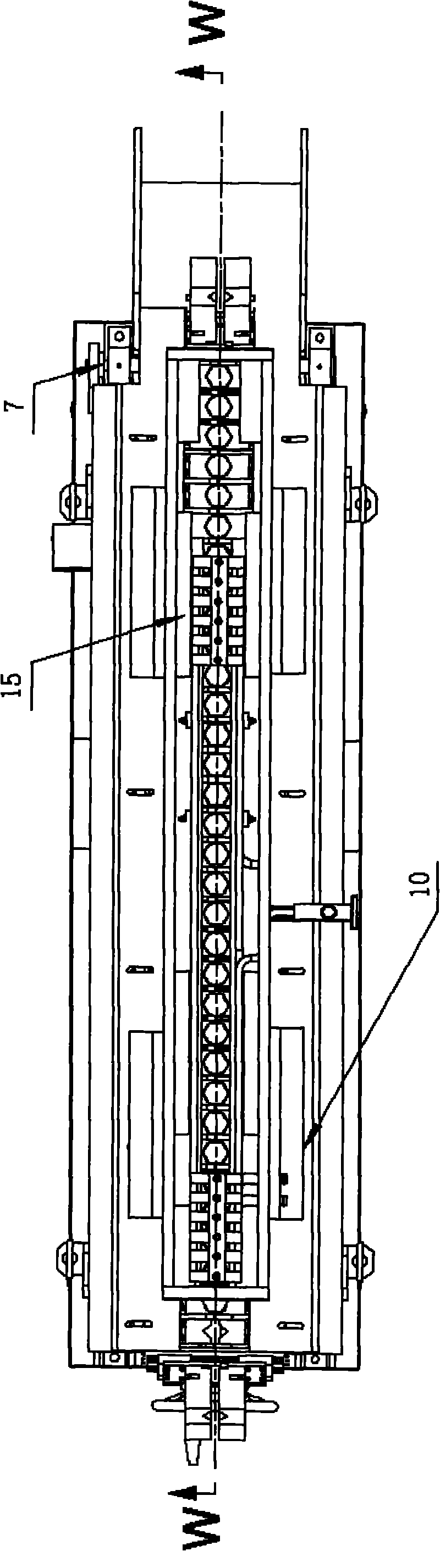
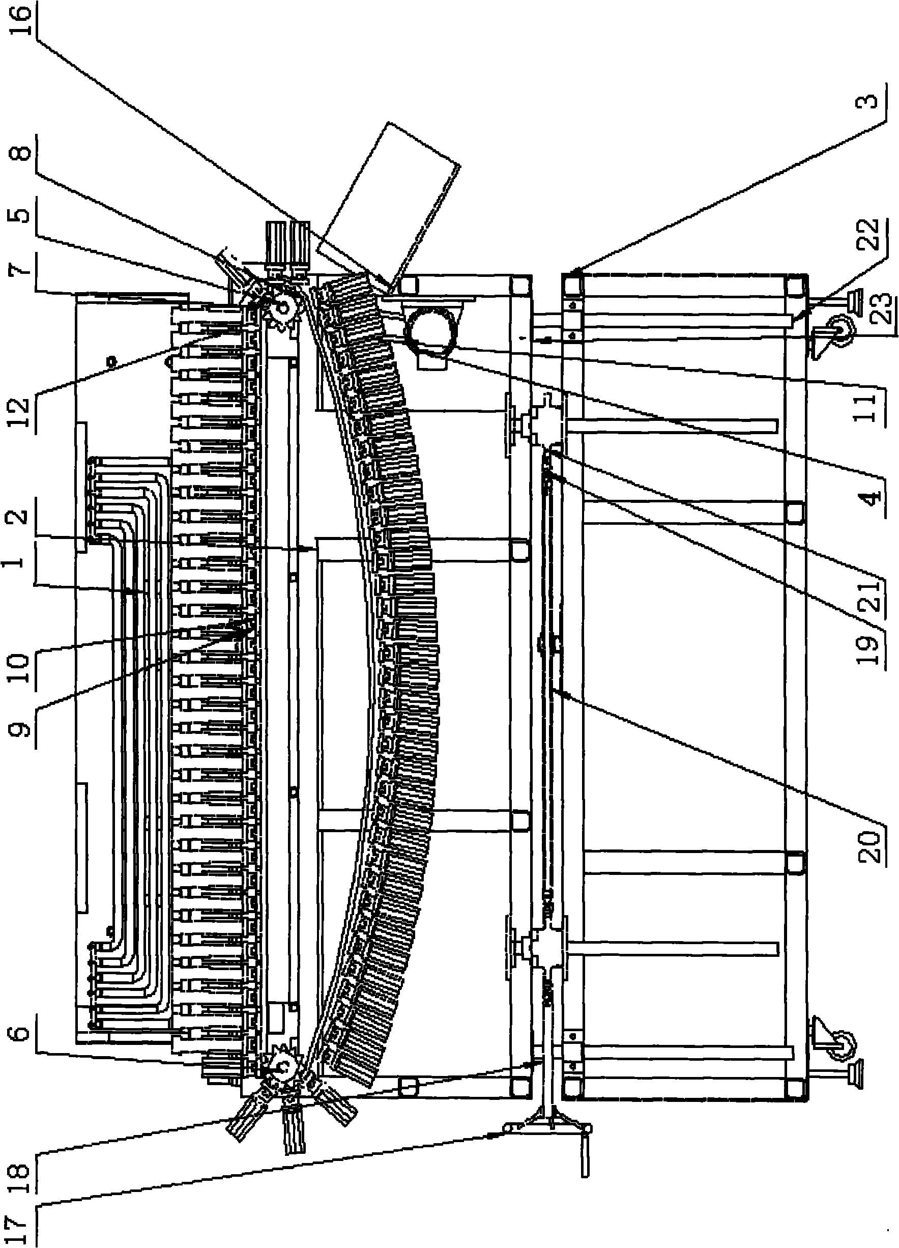
[0024] figure 1 It is a top view of the vertical feeder of the present invention; figure 2 for figure 1 W-direction view; image 3 It is a top view of the structure of the conveying device of the present invention.

[0025] Such as Figure 1 to Figure 3 Shown: the terminal induction heating device, including a U-shaped heating furnace 1 with an inverted cross section and a vertical conveyor, wherein the heating furnace 1 is located on the upper part of the vertical conveyor, and its U-shaped mouth is connected to the vertical conveyor The feeding ports of the machine correspond to each other. In addition, the vertical conveyor includes a transmission device, a feeding device, a lifting device, a positioning guide device, a frame 2 and a lifting platform 3, and the lifting device is arranged on the lifting platform 3. The transmission The device, the feeding device and the positioning and guiding device are arranged on the frame 2, and the frame 2 is located at the top of ...


PUM


Abstract

The invention discloses an end induction heating device comprising a U-shaped heating furnace with a reverse cross section and a vertical-type conveyer. The heating furnace is located on the upper part of the vertical-type conveyer; a U-shaped port of the heating furnace corresponds to a chucking port of the vertical-type conveyer; besides, the vertical-type conveyer comprises a transmission device, a conveying device, a lifting device, a positioning and guiding device, a stand and a lift rack, wherein the lifting device is arranged on the lifting rack; the transmission device, the conveying device and the positioning and guiding device are arranged on the stand; and the stand is located on the upper part of the lifting rack. The invention has simple structure, is easy to operate, ensures that workpieces are arranged sequentially in the heating process under the coactions of a conveying chain and a V-shaped block and can successfully enter the U-shaped heating furnace, can control the heating time and the heating surface favorably, ensures the thermal treatment quality of the workpieces, and can be used for heating the step sections of ladder cylindrical or square materials and other materials that can be clamped by a V shape.

Description

technical field [0001] The invention relates to a heating device, in particular to a heating device capable of automatic feeding, and belongs to the technical field of automatic processing. Background technique [0002] We know that there are threads on the surface of the screw, and heat treatment should be carried out on the surface to increase its strength and toughness. The traditional heat treatment method is to send the screws with very messy discharge into the heating furnace for heat treatment. The heating is uneven, and the heating time and heating degree are difficult to control, so that the heat treatment quality of the workpiece cannot meet the requirements. Contents of the invention [0003] In order to overcome the deficiencies of the prior art, the purpose of the present invention is to provide a terminal induction heating device with simple structure, high working efficiency, uniform heating of the workpiece and good heat treatment effect. [0004] The pres...

Claims


Application Information

Patent Timeline
Patent Type & Authority Applications(China)
IPC IPC(8): C21D9/00C21D1/10
CPCY02P10/25
Inventor 阙伯勋
Owner FIVE POWER ELECTRICAL TECHKUNSHAN
Why Eureka
Try Eureka