Workpiece temperature field determination method and heat treatment parameter determination method

A determination method and technology of temperature field, applied in the field of determination of workpiece temperature field, can solve problems such as energy consumption, waste of process time, long holding time, poor performance of workpiece, etc., to ensure heat treatment quality, reduce energy consumption, and improve process efficiency Effect

Inactive Publication Date: 2017-05-17
CHINA ERZHONG GRP DEYANG HEAVY IND
View PDF1 Cites 0 Cited by
  • Summary
  • Abstract
  • Description
  • Claims
  • Application Information

AI Technical Summary

Problems solved by technology

However, the above-mentioned holding time will change due to the size and shape of the workpiece, resulting in the inability to determine the optimal heat treatment temperature curve in the process.
If the holding time of the w

Method used


Image

  • Workpiece temperature field determination method and heat treatment parameter determination method
  • Workpiece temperature field determination method and heat treatment parameter determination method
  • Workpiece temperature field determination method and heat treatment parameter determination method

Examples


Embodiment Construction

[0024] Below in conjunction with accompanying drawing and embodiment the present invention is further described:

[0025] The method for determining the temperature field of a workpiece comprises the steps of: establishing a three-dimensional model of the workpiece in computer software; importing the model into a finite element analysis simulation software, setting parameters for temperature simulation calculation for the model; and further comprising the following steps in sequence:

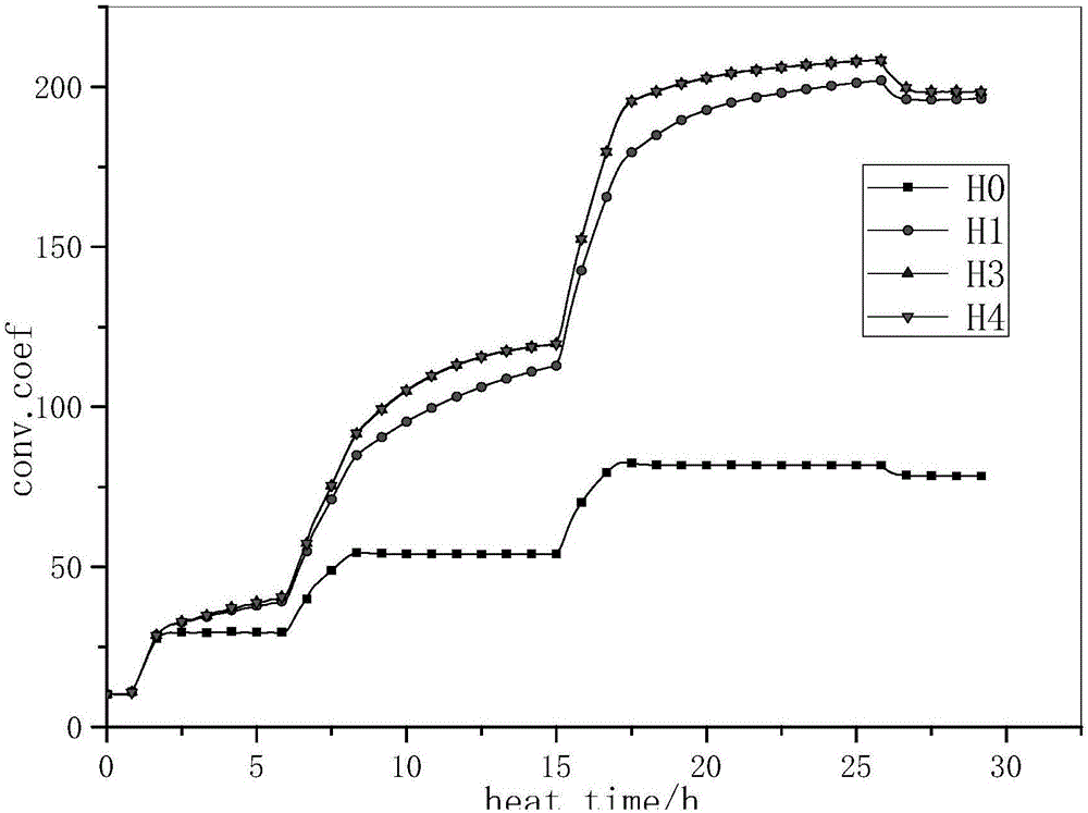
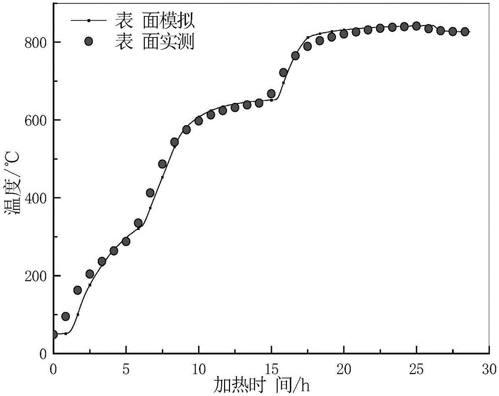
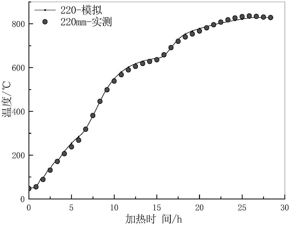
[0026] A. The heating temperature curve of the workpiece is T w , the workpiece surface heat transfer coefficient is H;

[0027] According to the fitting formula of air-cooled surface heat transfer coefficient:

[0028] H=2.2×(T w -T c ) 0.25 +4.6×10 -8 ×(T w 2 +T c 2 )×(T w +T c ) formula one;

[0029] In order:

[0030] The first iteration computes:

[0031] Let T w =f(t), T c = current room temperature, substituted into formula 1 to calculate the first set of heat transfer coe...


PUM


Abstract

The invention relates to a workpiece temperature field determination method. The workpiece temperature field determination method comprises the steps of establishing a three-dimensional model of a workpiece; and conducting iterative computation for multiple times through a workpiece air-cooled surface heat exchange coefficient fitting formula and finite element analysis and simulation software. Surface temperature functions close to true values are obtained, and subsequently a temperature field of the workpiece can be calculated. After the temperature filed is determined through the method, a proper heat treatment process can be determined; efficiency of the heat treatment procedure is improved; and product quality is guaranteed.

Description

technical field [0001] The invention relates to a method for determining the temperature field of a workpiece and a method for using the determined temperature field to guide the determination of heat treatment parameters. Background technique [0002] Workpieces produced by casting, forging and other processes usually require heat treatment to meet the requirements of use. For example, when a large workpiece is heat treated, it needs to be kept at the austenitizing temperature for at least enough time to ensure that the core and surface of the workpiece are completely transformed into austenite. However, the above-mentioned holding time will change due to the different sizes and shapes of the workpieces, resulting in the inability to determine the optimal heat treatment temperature curve in the process. If the holding time of the workpiece is insufficient, the heat treatment effect will be unsatisfactory and the performance of the workpiece will be poor; or if the holding ...

Claims


Application Information

Patent Timeline
IPC IPC(8): C21D11/00G06F17/50
CPCC21D11/00G06F30/23G06F2119/08
Inventor 杨运民李其
Owner CHINA ERZHONG GRP DEYANG HEAVY IND
Why Eureka
Try Eureka