
Rapid demolding method after press quenching of synchronous ring and synchronous ring press quenching device thereof

A synchronous ring and demoulding technology, which is applied in the direction of quenching device, process efficiency improvement, furnace, etc., can solve problems affecting product quality, mandrel and workpiece damage, and affecting production progress, so as to maintain heat treatment quality and achieve huge economic benefits , the effect of improving production efficiency

Pending Publication Date: 2022-05-10
株洲市湘宁高中频设备有限责任公司
View PDF8 Cites 1 Cited by
  • Summary
  • Abstract
  • Description
  • Claims
  • Application Information

AI Technical Summary

Problems solved by technology

In the manufacturing process of the synchronous ring, pressure quenching is an essential process. Due to the need for heat treatment, the synchronous ring is greatly deformed
[0003] The existing synchronous ring quenching tooling includes a lower mold, an upper mold and a quenching mandrel. When working, the workpiece is placed on the quenching mandrel, the lower mold and the upper mold are clamped, and then quenched. However, after quenching, the synchronous ring workpiece will be fixed on the quenching mandrel. On the mandrel, it is not easy to remove, which will affect the processing of subsequent workpieces and affect the production progress, and even to pull out the workpiece will cause certain damage to the mandrel and workpiece, affecting product quality

Method used


Image

  • Rapid demolding method after press quenching of synchronous ring and synchronous ring press quenching device thereof

Examples


Embodiment 1

[0024] In the method of rapid demoulding of the synchronous ring after press quenching in this embodiment, the outer end of the synchronous ring workpiece after press quenching is heated by a quenching inductor, the heating temperature is 110~130°C, and the heating time is 10~30S. In the example, the preferred heating temperature is 120°C and the heating time is 15S. After heating, pull the mandrel with external force and pull out the synchronous ring workpiece.

Embodiment 2

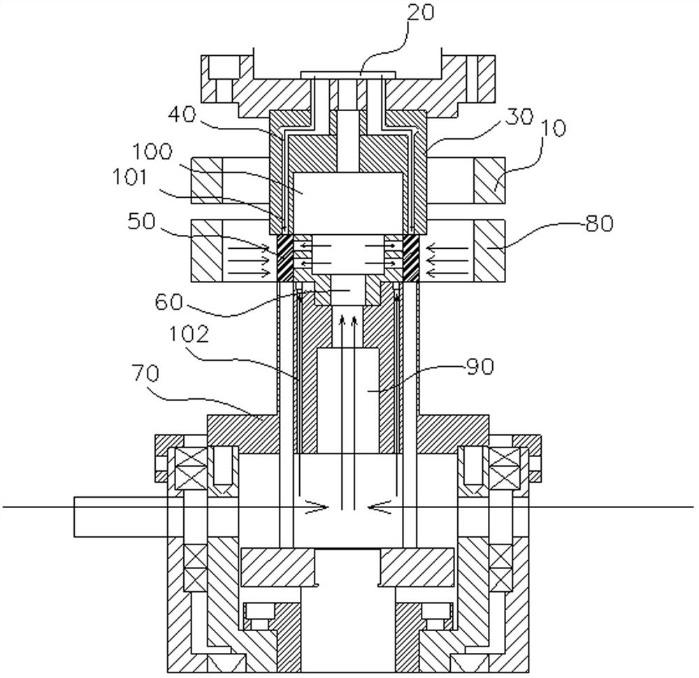
[0026] Such as figure 1 As shown, the synchronous ring press quenching device in this embodiment includes a lower die 70, an upper die 30 and a quenching mandrel 60; , the bottom of the upper mold 30 is provided with a core mold 60, the upper mold is provided with a cooling water channel 40, the outer periphery of one end of the upper mold 30 close to the core mold 60 is provided with an inductor 10 electrically connected to the power supply transformer, and the outer periphery of the core mold is provided with a spray nozzle. Water circle 80, water spray circle 80 comprises inner circle and outer circle, and inner circle and outer circle form annular quenching spray chamber, and the water spray velocity and water spray time of water spray circle 80 are controlled by controller.

[0027] The outer side of the lower die 70 is provided with a push rod 90, and the push rod 90 pushes out the mandrel 60 through the cylinder, so that the synchronized ring workpiece 50 to be quenched...


PUM


Abstract

The invention discloses a rapid demolding method for a synchronous ring after pressure quenching and a synchronous ring pressure quenching device thereof. The synchronous ring pressure quenching device comprises a lower mold, an upper mold and a quenching core mold, the upper die and the lower die are oppositely arranged, the upper die is installed on the upper pressing die connecting base, a core die is arranged at the bottom of the upper die, the upper die is provided with a cooling water channel, an inductor electrically connected with a power supply transformer is arranged on the periphery of the end, close to the core die, of the upper die, and a water spraying ring is arranged on the periphery of the core die and comprises an inner ring and an outer ring. The inner ring and the outer ring form an annular quenching spraying cavity, and the water spraying flow speed and the water spraying time of the water spraying ring are controlled by a controller. A lower die, an upper die and a quenching core die are arranged; the inductor is arranged on the periphery of the end, close to the core mold, of the upper mold, so that a product on the quenched core mold is preheated, demolding is facilitated, and the mold and a workpiece cannot be strained.

Description

technical field [0001] The invention belongs to the technical field of industrial machinery, and more specifically relates to a quick demoulding method for a synchronous ring after press quenching and a synchronous ring press quenching device. Background technique [0002] The synchronizer ring is an important part of the synchronizer. The function of the synchronizer is to ensure smooth shifting without impact and reduce shifting force. In the manufacturing process of the synchronous ring, pressure quenching is an essential process. Due to the need for heat treatment, the synchronous ring is greatly deformed. [0003] The existing synchronous ring quenching tooling includes a lower mold, an upper mold and a quenching mandrel. When working, the workpiece is placed on the quenching mandrel, the lower mold and the upper mold are clamped, and then quenched. However, after quenching, the synchronous ring workpiece will be fixed on the quenching mandrel. On the mandrel, it is no...

Claims


Application Information

Patent Timeline
Patent Type & Authority Applications(China)
IPC IPC(8): C21D9/40C21D1/673C21D1/667C21D1/42
CPCC21D9/40C21D1/673C21D1/667C21D1/42Y02P10/25
Inventor 管文兵
Owner 株洲市湘宁高中频设备有限责任公司
Learn More