High-power electric power electronic capacitor with firm welding spots

A technology of power electronics and capacitors, which is applied in the field of high-power power electronic capacitors, can solve problems such as pulling wires, copper strip deformation, loosening or falling off of solder joints, etc., to improve the pass rate, prevent loosening or falling off, and ensure that it is not damaged Effect

Inactive Publication Date: 2013-04-03
ANHUI TONGFENG ELECTRONICS
View PDF6 Cites 2 Cited by
  • Summary
  • Abstract
  • Description
  • Claims
  • Application Information

AI Technical Summary

Problems solved by technology

Due to the large number of wires in the capacitor with this structure, during the capacitor assembly process, it will inevitably cause inconvenience to the core pack and the connection between the wires and the terminals, resulting in low production efficiency.
At the same time, considering the overcurrent capability of the wires, usually each capacitor core needs to use a single wire or multiple wires with a thicker wire diameter. The two methods will also further increase the difficulty of core group bundling and wire and terminal connection. , leading to lower production efficiency
There is another defect in this wire connection structure: after the core group and the wire are welded, an insulating tape needs to be wrapped around the outer surface of the core group to form an insulating layer. Since the cores of the capacitor are relatively loose, the bundled core group is During the handling and assembly process, it is very easy to pull the wires and cause the solder joints to loosen or fall off, resulting in damage to the transition performance of the capacitor and increasing the failure rate of the product
Therefore, during welding, the solder joints on the lead-out copper strips are densely distributed, and the lead-out copper strips will be deformed due to welding stress, and because the core group is large in size and heavy in weight, it is unavoidable to be subjected to vibration during the transportation, installation and use of the capacitor. Avoidance will cause the displacement of the core group, which is very likely to strain the rigid solder joints of the electrical connection between the lead-out copper strip and the gold-sprayed surface, and cause the solder joints of the lead-out copper strip, especially the solder joints where the welding stress is concentrated, to loosen Or fall off, resulting in damage to its overcurrent performance, which will also increase the failure rate of the product

Method used


Image

  • High-power electric power electronic capacitor with firm welding spots
  • High-power electric power electronic capacitor with firm welding spots
  • High-power electric power electronic capacitor with firm welding spots

Examples


Embodiment Construction

[0016] The following embodiment is used as an example for the power electronic capacitor on the STATCOM / SVG dynamic reactive power compensation and harmonic control device.

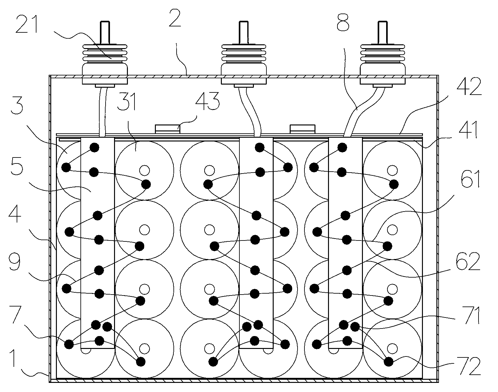
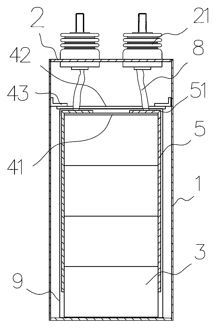
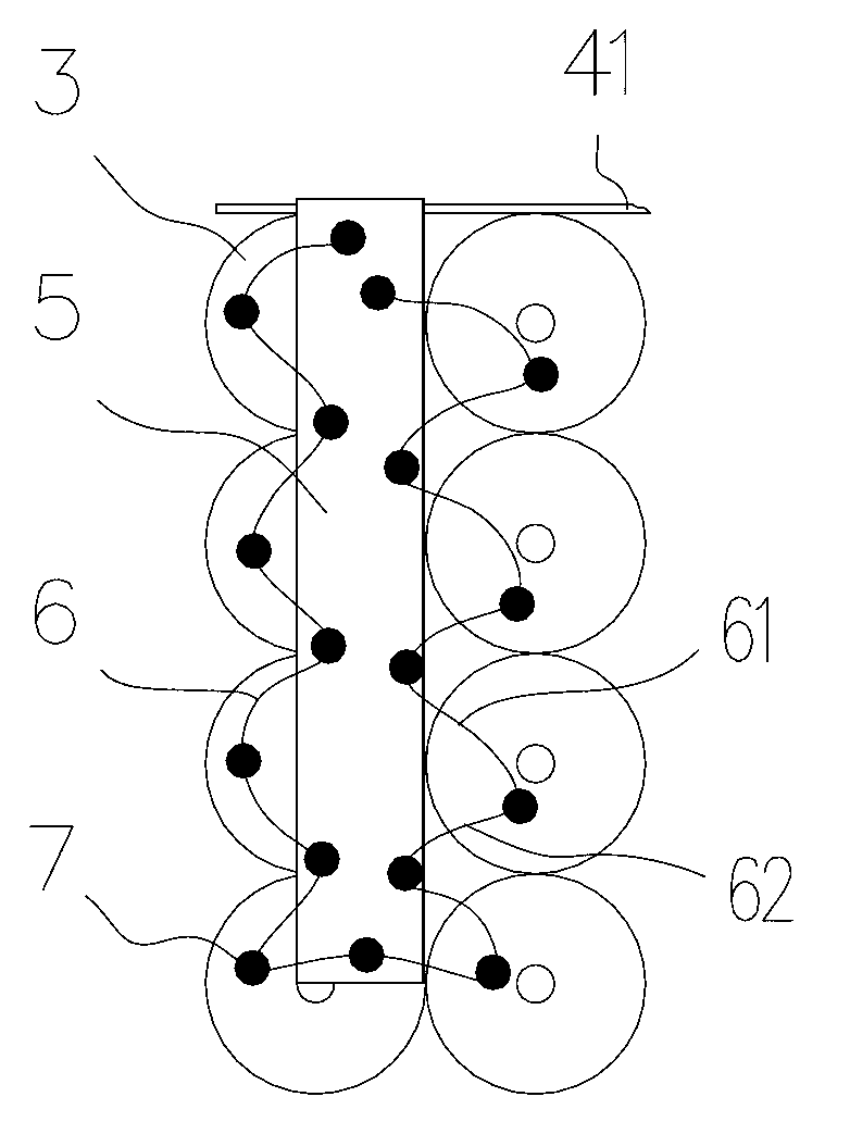
[0017] like figure 1 , figure 2 As shown, the present invention includes a cover plate assembly 2, a shell 1, and a core group 3; there are three groups of core groups 3, and each core group 3 is arranged side by side by two columns of capacitor cores, and each column of capacitor cores is composed of a plurality of capacitor cores 31 It is formed by stacking up and down; each core group 3 has a lead-out copper strip 5 on the gold-sprayed surface on both sides. Electrode 51; the gold-sprayed surface of each capacitor core 31 on each core group 3 is electrically connected with the lead-out copper strip 5 at the corresponding end respectively through a metal copper wire 6, and the wire 6 is electrically connected at two electrical connection solder joints 71, 72 The length between them is greater than th...


PUM


Abstract

The invention relates to a high-power electric power electronic capacitor with firm welding spots. The high-power electric power electronic capacitor with firm welding spots comprises a cover plate assembly, a casing and core groups fixed in the casing. Each group of the core groups are composed of a row of capacitor cores or two rows of capacitor cores arranged side by side, a lead-out copper strip is respectively arranged on metal sprayed surfaces of two sides of each core group, a metal sprayed surface of each capacitor core on each core group is electrically connected with the lead-out copper strip at the corresponding end through a wire, and length of the wire between the two electrically connected welding spots is longer than straight-line distance between the two welding spots. The lead-out copper strips are in flexible connection with the metal sprayed surfaces of the core groups through wires, displacement of the core groups cannot strain the welding spots on the core groups and the lead-out copper strips, and loosening or dropping of the welding spots can be effectively avoided.

Description

technical field [0001] The invention relates to an oil-immersed high-power power electronic capacitor using a cylindrical capacitor core, in particular to a high-power power electronic capacitor with firm solder joints. Background technique [0002] At present, oil-immersed high-power power electronic capacitors with cylindrical capacitor cores are commonly used in the market. One or more sets of cores are arranged in the casing, and each set of cores is arranged side by side with one or two rows of capacitor cores. The capacitor core is formed by stacking multiple capacitor cores up and down, and the gold-sprayed surface on both sides of each capacitor core is welded with wires electrically connected to the terminals on the cover plate assembly. Due to the large number of wires in the capacitor with this structure, during the capacitor assembly process, it will inevitably cause inconvenience to the bundle of the core group and the connection between the wires and the termin...

Claims


Application Information

Patent Timeline
Patent Type & Authority Applications(China)
IPC IPC(8): H01G4/38
Inventor 储松潮汪威杨波潘焱尧
Owner ANHUI TONGFENG ELECTRONICS
Why Eureka
Try Eureka