
Landing leg hydraulic cylinder piston and manufacturing process thereof

A hydraulic cylinder and piston technology, applied in the field of hydraulic cylinder piston and its manufacturing process, can solve problems such as oil leakage, wear, and strain on the inner wall of the cylinder barrel

Inactive Publication Date: 2010-02-10
李新桥
View PDF0 Cites 2 Cited by
  • Summary
  • Abstract
  • Description
  • Claims
  • Application Information

AI Technical Summary

Problems solved by technology

[0002] Traditional hydraulic cylinder pistons mainly use support rings to improve the bearing capacity and sealing performance of the hydraulic system, however, this structure has serious deficiencies
Since the piston needs to work for a long time under the action of high load, it is always required to use a wear-resistant material with higher hardness to make it. When the piston made of high hardness material is subjected to excessive lateral load, it is easy to cause the The strain and wear of the inner wall of the cylinder will eventually lead to oil leakage

Method used


Image

  • Landing leg hydraulic cylinder piston and manufacturing process thereof
  • Landing leg hydraulic cylinder piston and manufacturing process thereof

Examples


Embodiment Construction

[0011] The present invention will be further described below in conjunction with the accompanying drawings and embodiments.

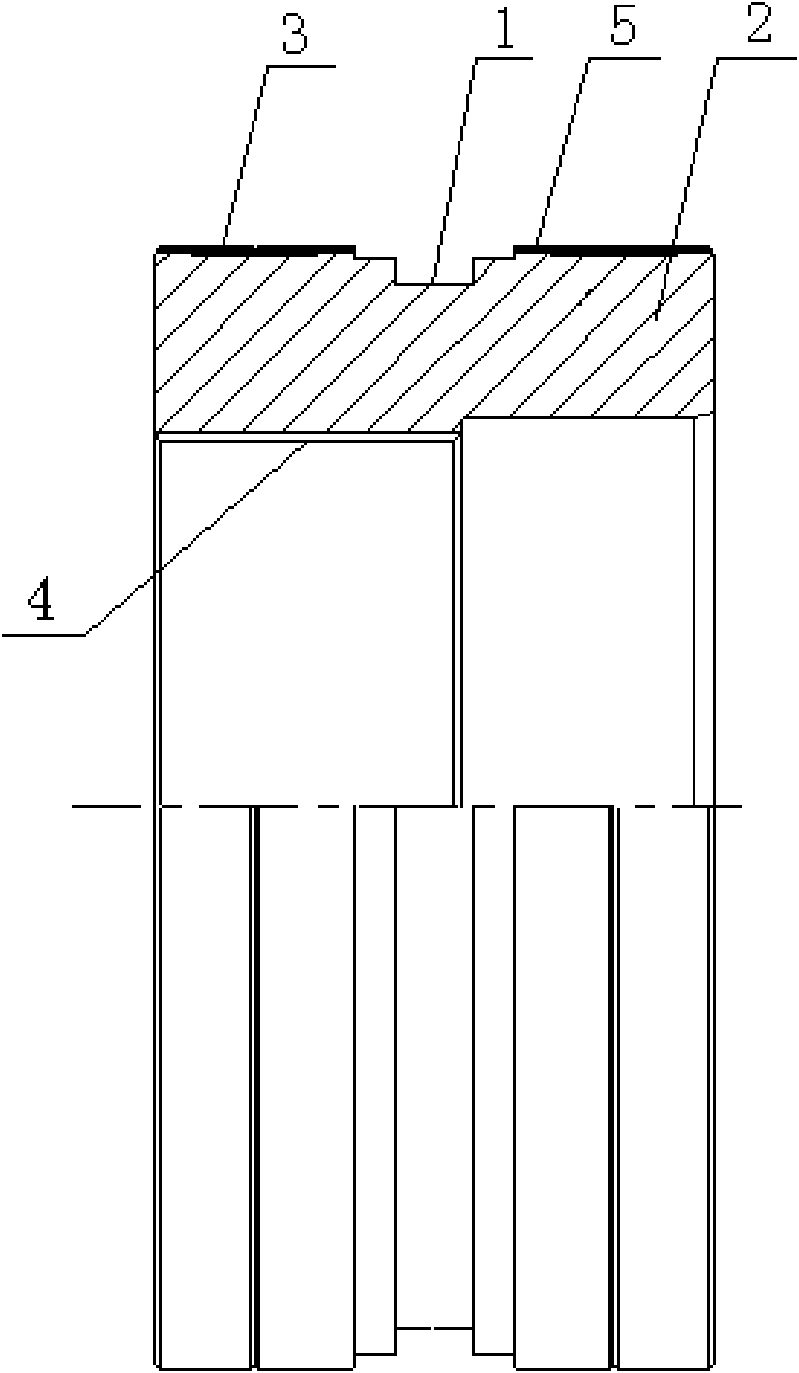
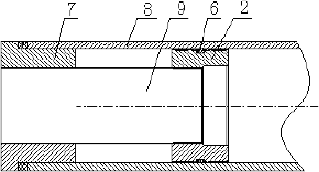
[0012] Referring to the accompanying drawings, this embodiment includes a piston body 2, an annular gasket groove 1 is provided on the outer circular surface of the middle part of the piston body 2, and a rubber gasket 6 for sealing is placed in the annular gasket groove 1, and the piston body on both sides of the annular gasket groove 1 The surface is processed with a welding process ring groove 5, and a copper fusion welding coating 3 is welded in the welding process ring groove 5, and the copper fusion welding coating is 1mm higher than the outer surface of the piston body 2; the piston body 2 is fixed to the piston rod 9 through the internal thread 4 .

[0013] Manufacturing process: firstly, the annular gasket groove 1 and the welding process ring groove 5 are turned on the outer surface of the piston body 2; then, the brazing adhesive and copper s...


PUM


Abstract

The invention relates to a landing leg hydraulic cylinder piston and a manufacturing process thereof. The landing leg hydraulic cylinder piston comprises a piston body and a piston rod, wherein the surface of the middle part of the piston body is provided with an annular gasket groove, a rubber gasket playing the role of sealing is arranged in the annular gasket groove, welding technology annulargrooves are processed on the surfaces of the piston body on both sides of the annular gasket groove, and a copper soluble solder plating is welded in each of the welding technology annular grooves andis projected out from the surface of the excircle of the piston body by 0.8mm to 1.2mm; and the piston body is fixedly connected with the piston rod by internal screw threads. The landing leg hydraulic cylinder piston has long service life, and can not damage the inner wall of a cylinder barrel of a hydraulic cylinder by pulling even under the circumstance of higher unbalance loading.

Description

technical field [0001] The invention relates to a hydraulic cylinder piston and a manufacturing process thereof, in particular to an outrigger hydraulic cylinder piston and a manufacturing process thereof. Background technique [0002] Traditional hydraulic cylinder pistons mainly use support rings to improve the bearing capacity and sealing performance of the hydraulic system. However, this structure has serious shortcomings. Since the piston needs to work for a long time under the action of high load, it is always required to use a wear-resistant material with higher hardness to make it. When the piston made of high hardness material is subjected to excessive lateral load, it is easy to cause the The strain and wear of the inner wall of the barrel will eventually lead to oil leakage. Contents of the invention [0003] The purpose of the present invention is to overcome the above-mentioned defects existing in the existing hydraulic cylinder pistons, to provide a hydrauli...

Claims


Application Information

Patent Timeline
Patent Type & Authority Applications(China)
IPC IPC(8): F16J1/01F16J1/12
Inventor 曾广胜江太君刘跃军石璞
Owner 李新桥
Learn More