Coupling type injector pressing device

A compression device and fuel injector technology, which is applied in fuel injection devices, charging systems, machines/engines, etc., can solve the problem of uneven force on the fuel injector, affecting the normal operation of the fuel injector, and large volume of the fuel injector And other issues

Inactive Publication Date: 2010-10-20
DONGFENG CHAOYANG DIESEL ENGINE
View PDF0 Cites 6 Cited by
  • Summary
  • Abstract
  • Description
  • Claims
  • Application Information

AI Technical Summary

Problems solved by technology

However, since the structure of the cylinder head of a diesel engine varies with the model, the pressure plate of the fuel injector will need to derive various forms of pressing devices during the matching process of the cylinder head, but this will undoubtedly increase the variety of models of the pressure plate of the fuel injector. and complexity
At present, there are two forms of the fuel injector pressure plate, one is that the pressure plate and the fuel injector body are cast into one body, this structure is not easy to guarantee the machining accuracy, and the electronically controlled fuel injector is rarely used, and at the same time, the fuel injector is relatively large; The other is the plug-in pressure plate, which processes two small end faces of the cylindrical fuel injector, and then inserts the pressure plate into the groove. The defect of this compression method is that the force on the cantilever of the pressure plate makes the overall force of the fuel injector uneven. Affect the normal operation of the injector

Method used


Image

  • Coupling type injector pressing device
  • Coupling type injector pressing device
  • Coupling type injector pressing device

Examples


Embodiment Construction

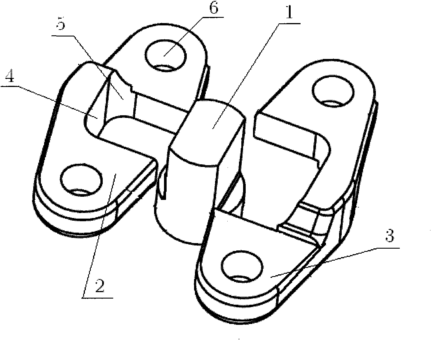
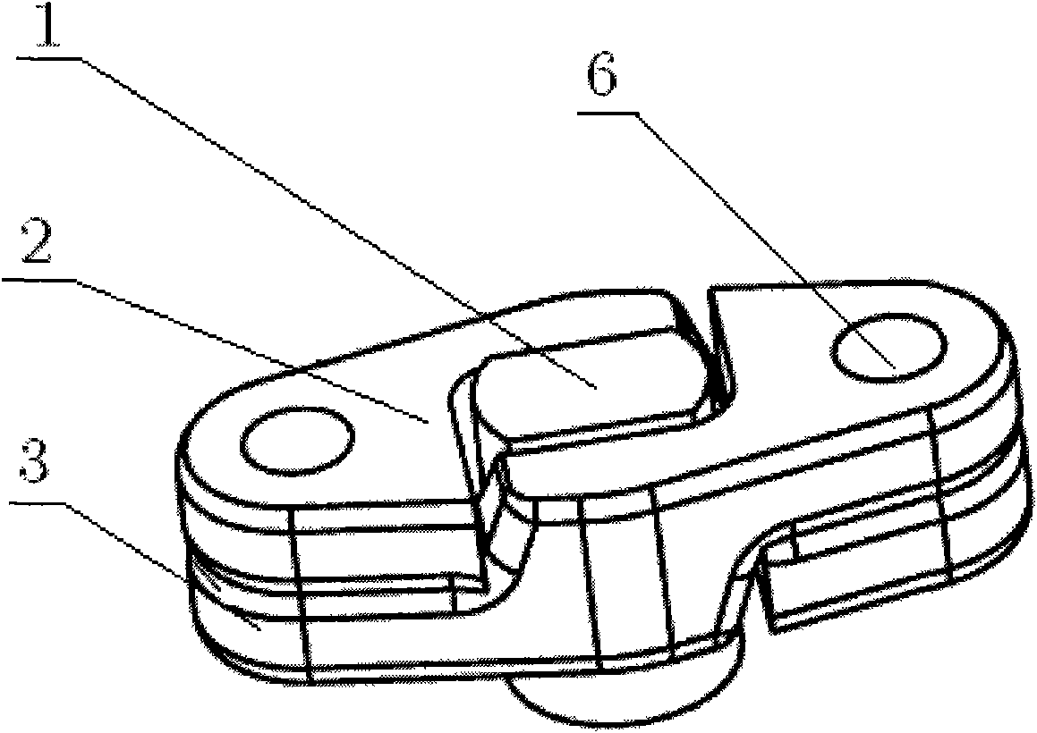
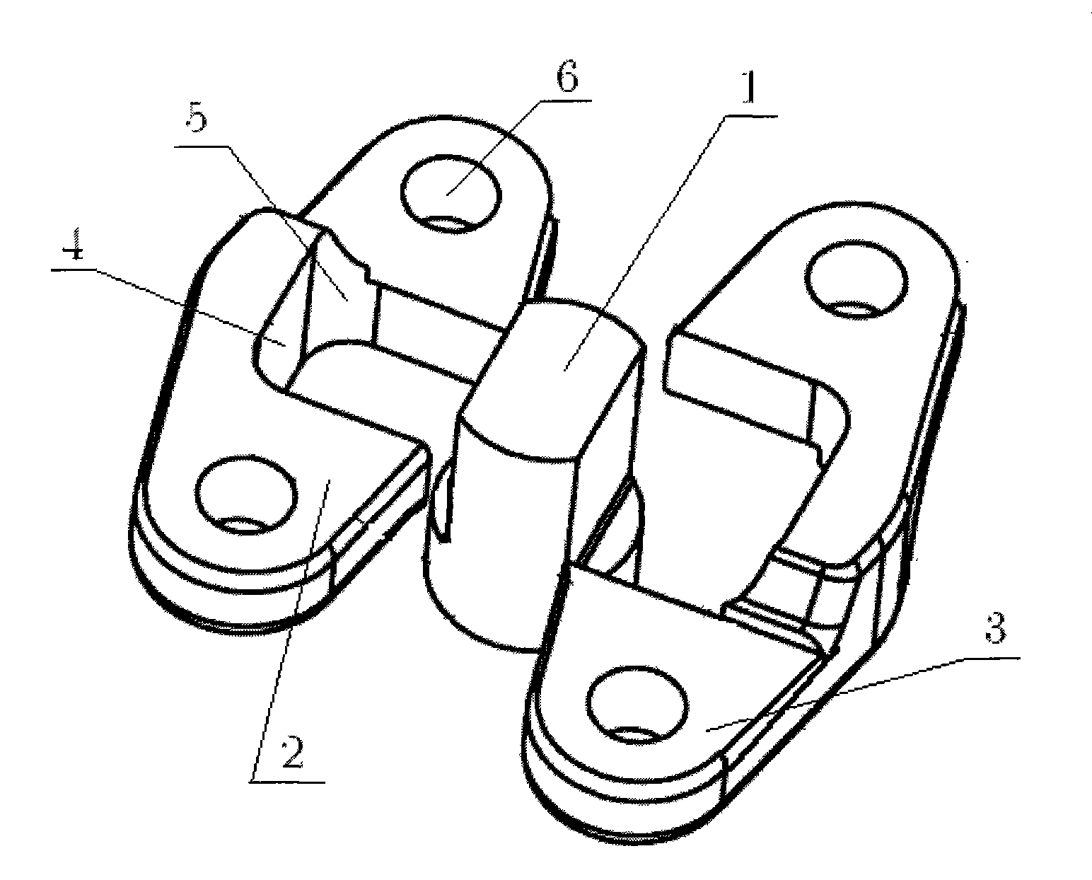
[0007] The structural principles of the present invention will be further described below in conjunction with the accompanying drawings and through embodiments. The coupling type fuel injector pressing device is composed of a pressure plate and a fuel injector. The cylindrical fuel injector 1 has two mutually parallel elevations, and the cylindrical fuel injector 1 is coupled and fixed by the sub-pressure plate 2 and the female pressure plate 3 . The structure and size of the sub-press plate 2 and the mother press plate 3 are completely symmetrical (such as figure 1 ). The height of the two parallel facades of the cylindrical fuel injector 1 is equal to the elevation pressing surface 4 on the sub-press plate 2 and the mother press plate 3; Cylindrical fuel injector 1 cylinders have equal radii. Fastening bolt holes 6 are provided at both ends of the sub-press plate 2 and the mother press plate 3 . The thickness of the pressing surface 4 and the arc pressing surface 5 of the...


PUM


Abstract

The invention discloses a diesel injector pressing device which comprises pressing plates and an injector, wherein the cylindrical injector is provided with two parallel vertical surfaces, the cylindrical injector is coupled, installed and fixed by a sub-pressing plate and a mother pressing plate, and the structures and the sizes of the two pressing plates are fully symmetrical; the height of the two parallel vertical surfaces of the cylindrical injector is equal to that of a vertical surface pressing surface on the sub pressing plate and the mother pressing plate; the processing radius of a cambered surface pressing surface on the sub pressing plate and the mother pressing plate is equal to that of a cylinder of the cylindrical injector; fastening bolt holes are arranged at two ends of the two pressing plates; and the thickness of the vertical surface pressing surface and the cambered surface pressing surface of the pressing plates is twice as much as that of each of the bolt holes at two ends of the pressing plates. The invention has the advantages that the two pressing plates are coupled and assembled to solve the problems of difficult assembly and uneven stress for an integrated pressing plate, the sub-pressing plate and the mother pressing plate can together bear the pre-tightening force of bolts and the pulse impact force from the inner part of the cylinder, and the device of the invention can be widely applied to fix and assemble injectors on various kinds of diesel cylinder covers.

Description

technical field [0001] The invention belongs to an accessory part of an internal combustion engine, in particular to a pressing device for a fuel injector of a diesel engine. Background technique [0002] The fuel injector of diesel engine is a very critical part in the internal combustion engine. Although the pressure plate of the fuel injector is small, it has a great relationship. If the design is not reasonable, the fuel injector will become loose, the engine will work unstable, and even cause a large number of quality accidents. At present, the assembly and connection of the fuel injector and the cylinder head generally adopt the method of additional parts, that is, the pressure plate of the fuel injector. Once the fuel injector is finalized, the structure and size of the pressure plate will not be greatly changed due to the strict requirements of the process and other aspects. However, since the structure of the cylinder head of a diesel engine varies with the model, ...

Claims


Application Information

Patent Timeline
Patent Type & Authority Applications(China)
IPC IPC(8): F02M61/14
Inventor 庞华廷陶海峰
Owner DONGFENG CHAOYANG DIESEL ENGINE
Why Eureka
Try Eureka