Centrifugal water pump

A centrifugal, water pump technology, applied in the hydraulic field, can solve the problems of energy waste, complex structure, can not meet the high-efficiency water pump, etc., achieve uniform flow rate, less hydraulic loss, and meet the effect of high-efficiency and energy-saving water pumps

Inactive Publication Date: 2010-10-20
CHINA NORTH IND GRP NO 70 RES INST
View PDF5 Cites 11 Cited by
  • Summary
  • Abstract
  • Description
  • Claims
  • Application Information

AI Technical Summary

Problems solved by technology

[0002] At present, the centrifugal water pump mainly adopts the impeller of the single-arc blade type, and the blades of the impeller of the water pump are generated through a simple arc surface. Usually, the number of blades is 4 to 5. Although the structure of this type of impeller is simple, its efficiency is low. It cannot meet the requirements of high-efficiency water pumps; the volute of the water pump adopts a simple Archimedes spiral form; the suction chamber of the water pump adopts a straight conical axial suction chamber, and the taper is generally 8°, which seriously affects the efficiency of the water pump
[0003] With the increasingly strict requirements of the country for energy saving and emission reduction, the efficiency of the domestic water pump industry, especially the water pump in the agricultural irrigation industry, is generally around 30% to 45%. The price of a single water pump is generally thousands of yuan, and the structure is complicated

Method used


Image

  • Centrifugal water pump
  • Centrifugal water pump
  • Centrifugal water pump

Examples


Embodiment Construction

[0012] The preferred embodiments of the present invention will be further described below in conjunction with the accompanying drawings.

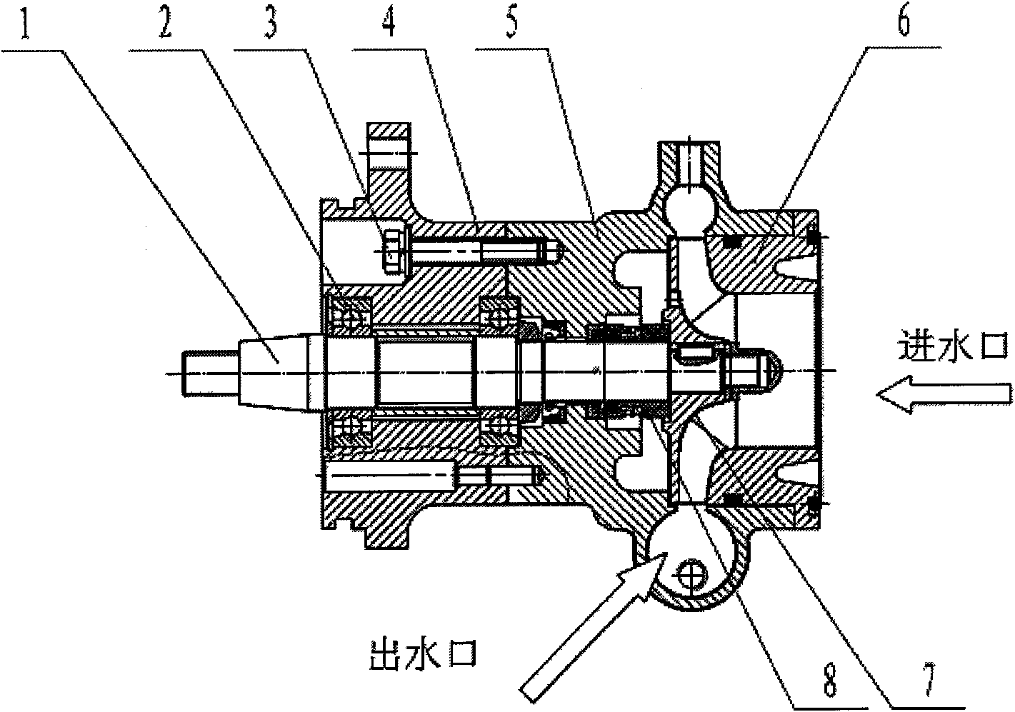
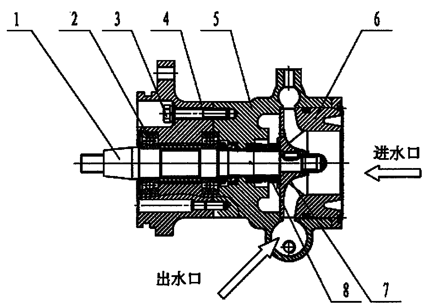
[0013] Such as figure 1 As shown, a centrifugal water pump includes a transmission shaft 1, a bearing 2, a fastener 3, a bearing seat 4, a volute 5, a water inlet plate 6, an impeller 7 and a mechanical seal 8, and the bearing 2 is installed on the bearing seat with interference 4, the transmission shaft 1 and the inner ring of the bearing 2 are installed with interference, there are two fasteners 3, the volute 5 is connected to the bearing seat 4 through a fastener 3, and the mechanical seal 8 is installed in the seat hole of the volute 5 , the transmission shaft 1 passes through the shaft hole of the mechanical seal 8 , the impeller 7 is in interference connection with the transmission shaft 1 , and the water inlet connection plate 6 is connected with the volute 5 through another fastener 3 . The water outlet of the volute 5 adopts a rad...


PUM


Abstract

The invention relates to a centrifugal water pump, belonging to the hydraulic technical field. The centrifugal water pump comprises a transmission shaft, a bearing, a fastening piece, a bearing seat, a volute, an inlet water pan, an impeller and a mechanical seal. The impeller consists of long blades and short blades. Five long blades and five short blades are arranged in a spacing way. The diameter of the middle shaft hole of the impeller is 18mm, the diameter of a hub is 24mm, the outer diameter of the impeller is 133.6mm, the length of each long blade is 46.8mm, the length of each short blade is 26.8mm, the diameter of the inlet of the long blade and the short blade is 66mm, the setting angle of the inlet of the long blade and the short blade is 36 degrees, the height of the inlet of the long blade and the short blade is 17mm, the thickness of the long blade and the short blade is 3.5mm, the setting angle of the outlet of the long blade and the short blade is 45 degrees and the height of the outlet of the long blade and the short blade is 10.3mm. The runner of the volute is matched with the impeller. The taper of the suction chamber of the inlet water pan is 12.5 degrees. The invention has the advantages of high efficiency, energy saving, good workability, light weight and small volume.

Description

technical field [0001] The invention belongs to the technical field of hydraulic pressure, and in particular relates to a centrifugal water pump. Background technique [0002] At present, the centrifugal water pump mainly adopts the impeller of the single-arc blade type, and the blades of the impeller of the water pump are generated through a simple arc surface. Usually, the number of blades is 4 to 5. Although the structure of this type of impeller is simple, its efficiency is low. It cannot meet the requirements of high-efficiency water pumps; the volute of the water pump adopts a simple Archimedes spiral form; the suction chamber of the water pump adopts a straight conical axial suction chamber, and the taper is generally 8°, which seriously affects the efficiency of the water pump. [0003] With the increasingly strict requirements of the country for energy saving and emission reduction, the efficiency of the domestic water pump industry, especially the water pump in the...

Claims


Application Information

Patent Timeline
Patent Type & Authority Applications(China)
IPC IPC(8): F04D29/22F04D29/24F04D29/42
CPCF04D29/24
Inventor 王清旭陈晓飞魏志明谭建松黄晓东
Owner CHINA NORTH IND GRP NO 70 RES INST
Why Eureka
Try Eureka