Thread cartridge balanced valve

A threaded cartridge and balance valve technology, applied in fluid pressure actuators, servo motor components, mechanical equipment, etc., can solve problems such as system instability, low-frequency jitter, and different connection sizes, so as to facilitate serialization and reduce weight , the effect of easy installation

Inactive Publication Date: 2010-10-20
ZHENJIANG DALI HYDRAULIC MOTOR
View PDF5 Cites 26 Cited by
  • Summary
  • Abstract
  • Description
  • Claims
  • Application Information

AI Technical Summary

Problems solved by technology

The existing hydraulic balance valve is mainly composed of control valve and main valve. There are two common types in construction machinery: single-stage and pilot-operated. The single-stage main valve and control valve are connected in parallel, and the pilot-operated main valve and control valve are Nested connection, but the above-mentioned two kinds of hydraulic balance valves have a common disadvantage in terms of performance. When the hydraulic load-bearing system is descending under load, it is difficult for the spool opening of the balance valve to be stabilized at a certain opening size, which makes the load occur during the descent. The phenomenon of low-frequen

Method used


Image

  • Thread cartridge balanced valve
  • Thread cartridge balanced valve
  • Thread cartridge balanced valve

Examples


Embodiment 1

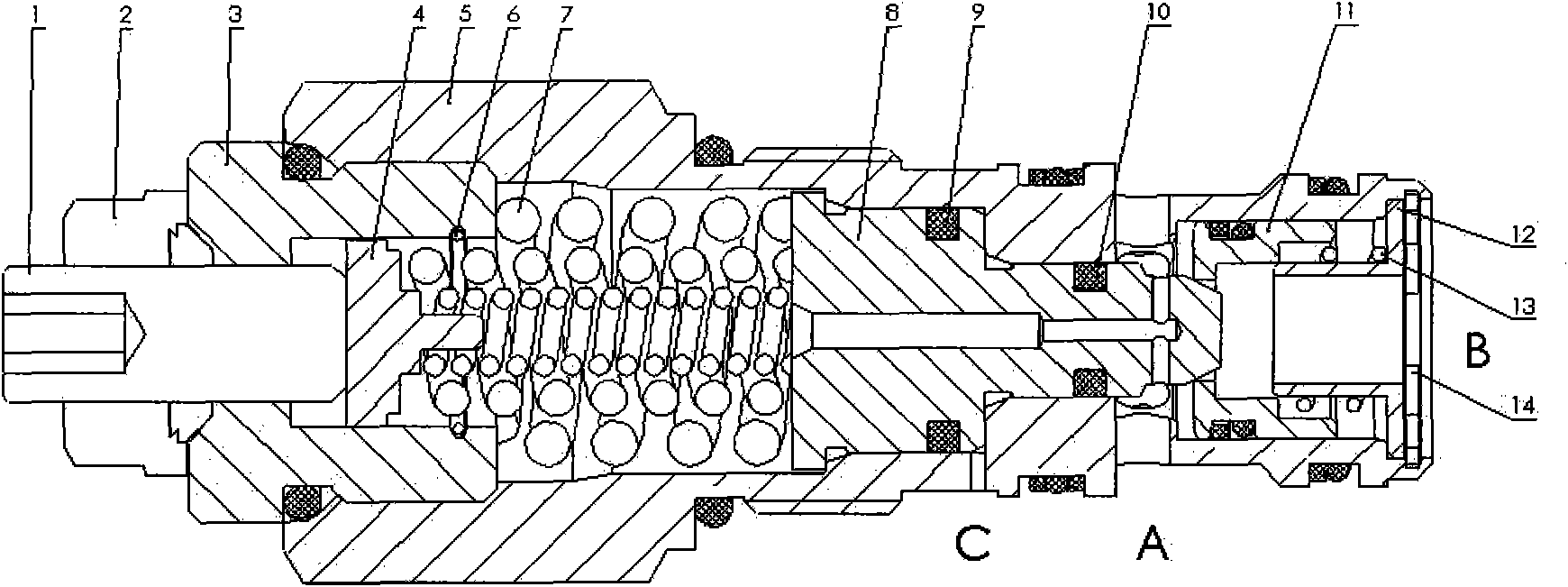
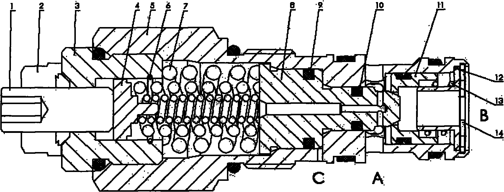
[0016] The basic structure of the threaded cartridge balance valve of this embodiment is as follows: figure 1 As shown, the threaded cartridge balance valve is mainly composed of a sealing nut 2, a valve body 5, a spring set 7, a valve core 8, and a valve seat 11. The valve seat 11 is connected with the valve core 8 front and back, and forms a one-way control valve structure with the conical structure end of the valve core 8, while the pilot valve core is located at the other end of the valve core 8, which is stepped and connected to the valve body 5, The airtight cavity formed by the sealing rings 9 and 10 is connected with the control oil port C to form a pilot control oil circuit. The valve body 5 is in a cylindrical shape, and the sealing rings 9 and 10 are grey ring sealing structures.

[0017] The valve body 5 is connected with the valve core 8 through the spring group 7, the piston 4, and the valve cover 3 to form a multiple load-sensitive whole. The spring group 7 has ...


PUM


Abstract

The invention relates to a thread cartridge balanced valve which is applicable to a working condition with a mutative load and especially engineering machinery which requires load downlink controlling and makes an effect on balancing the load gravity and the load speed. The thread cartridge balanced valve comprises a valve body and a valve core, wherein the valve core is connected with the valve body through a spring set composed of a plurality of springs which are embedded with each other by screwing leftwards and rightwards respectively and have different rigidity to form a multi-load sensitive entirety. The valve core integrates the functions of the existing main valve core and the existing pilot valve core; the reaction speeds are completely consistent so that load is more stable during the descending process and no low-frequency shaking phenomenon occurs, thus guaranteeing the safe reliability of a system; and when a hose decompresses, the main valve core can automatically and rapidly close an oil channel between a main oil port B and a main oil port A, prevent the stall speed of the load from descending, and serve as a hydraulic lock.

Description

technical field [0001] The invention relates to a hydraulic balance valve, in particular to a threaded plug-in balance valve, which belongs to the technical field of hydraulic transmission. Background technique [0002] In modern large, medium and small hydraulic systems, various hydraulic balance valves or valve bodies with balance valve functions are widely used. The existing hydraulic balance valve is mainly composed of control valve and main valve. There are two common types in construction machinery: single-stage and pilot-operated. The single-stage main valve and control valve are connected in parallel, and the pilot-operated main valve and control valve are Nested connection, but the above-mentioned two kinds of hydraulic balance valves have a common disadvantage in terms of performance. When the hydraulic load-bearing system is descending under load, it is difficult for the spool opening of the balance valve to be stabilized at a certain opening size, which makes the...

Claims


Application Information

Patent Timeline
IPC IPC(8): F15B13/02
Inventor 柯贤胜楼峰盛玉川王志生纪立群
Owner ZHENJIANG DALI HYDRAULIC MOTOR
Why Eureka
Try Eureka