Liquid excess pressure energy recovery device

A technology of energy recovery and residual pressure, which is applied in the direction of fluid pressure actuation devices, fluid pressure actuation system components, mechanical equipment, etc., can solve the problems of bulky, decreased safety and stability, and heavy maintenance workload, etc., and achieve volumetric efficiency High, convenient design, simple structure

Active Publication Date: 2010-10-20
SUNUP ENVIRONMENTAL TECH CO LTD
View PDF6 Cites 39 Cited by
  • Summary
  • Abstract
  • Description
  • Claims
  • Application Information

AI Technical Summary

Problems solved by technology

Valve-controlled work exchanger (Worker Exchange), representative products include Work Exchanger Energy Recovery (DWEER) of Calder Company in Switzerland, Aqualyng's System of Denmark, PressureExchange System (PES) of Sigma Company of Germany, etc. These energy recovery devices are bulky and the main materials are made of It is made of precious and rare metal corrosion-resistant materials. In addition, the control valve switches frequently, and its switching volume is more than 1 million times per year. The maintenance workload is large and the safety

Method used


Image

  • Liquid excess pressure energy recovery device
  • Liquid excess pressure energy recovery device
  • Liquid excess pressure energy recovery device

Examples


Embodiment Construction

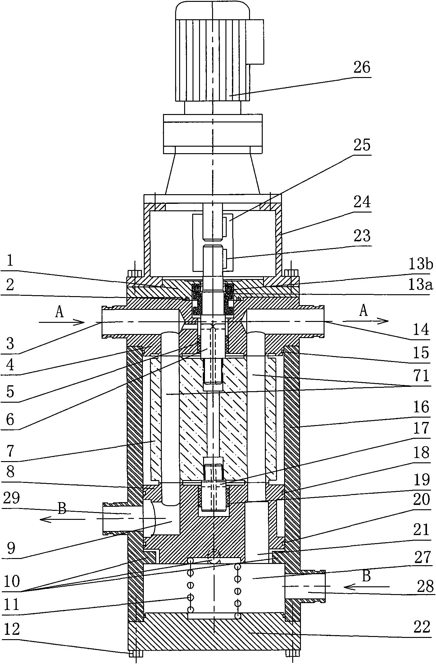
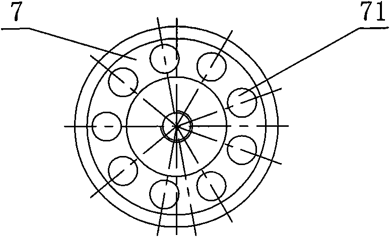
[0023] Refer to attached picture. The present invention includes a drive motor 26 and a rotating assembly, the rotating assembly includes: a moving ring 13a for mechanical sealing, a drive shaft 6, a rotor 7, and a driven shaft 17, and the rotor 7 is evenly provided with 9 drive shafts along the circumference. axially parallel flow channels 71 of the shaft;

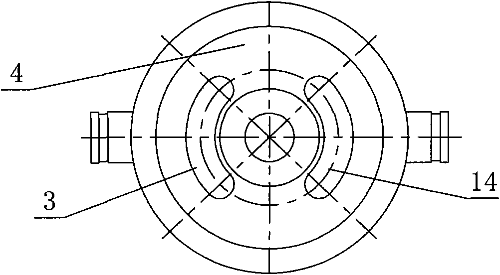
[0024] The pressure exchanger is also provided with a non-rotating assembly, which includes a mechanical seal cover 1, a static ring 13b for mechanical sealing, a fixed flow distribution plate 4, a floating flow distribution plate 8, a housing 16, a compression spring 11, Outer end cover 22 and bolts 12; the fixed flow distribution plate 4 is provided with a relatively low pressure fluid inlet 3, a relatively high pressure fluid outlet 14 and the shaft sleeve 5 of the drive shaft is installed, and the floating flow distribution plate 8 is provided with a relatively low pressure fluid Outlet 9, relatively high-pressure fl...


PUM


Abstract

The invention provides a liquid excess pressure energy recovery device. The device comprises a drive motor and a rotating assembly, wherein the rotating assembly comprises a rotating ring used for seal, a drive shaft, a rotor and a driven shaft; the rotor is provided with one or more flow channels which are parallel to the axial direction of the drive shaft; and a pressure exchanger is also provided with a fixed assembly, wherein the fixed assembly comprises a mechanical sealing cover, a static ring used for mechanical seal, a fixed valve plate, a floating valve plate, a shell, a compression spring, an outer end cover and a bolt. The liquid excess pressure energy recovery device of the invention has an energy recovery rate over 90 percent, has much higher energy recovery rate compared with pressure energy utilization devices such as a Francis pump, a Pelton turbine and the like which have the energy recovery rate of between 30 and 70 percent and need converting mechanical energy intermediately, has higher adaptability to working condition changes, and can also keep the energy recovery rate over 90 percent when the conditions such as flow rate, temperature and the like change.

Description

technical field [0001] The invention relates to a pressure energy recovery device in a fluid system. Background technique [0002] There are many forms of liquid residual pressure energy recovery devices, with great differences in structure and efficiency. According to the working principle, they can be divided into two categories: hydraulic turbine energy recovery devices and work exchange energy recovery devices. [0003] In the hydraulic turbine energy recovery device, the energy conversion process is pressure energy-mechanical energy (shaft work)-pressure energy. That is, mechanical energy is used as the intermediate link of fluid energy transmission, so it is also called mechanical energy intermediary technology. It entered the market in the late 1970s and early 1980s. Typical device types include Francis Pump and Pehon Wheel. For impellers and hydraulic turbines (Turbo Charger), etc., the energy recovery technology is affected by multiple conversions of energy. Althou...

Claims


Application Information

Patent Timeline
IPC IPC(8): F15B21/14
Inventor 蒋亚荣
Owner SUNUP ENVIRONMENTAL TECH CO LTD
Why Eureka
Try Eureka