Hydraulic electricity generation shock absorber of vehicle

A hydraulic power generation and shock absorber technology, which is applied in liquid shock absorbers, machines/engines, mechanical equipment, etc., can solve problems such as low reliability, difficult use of electric energy for vehicles, and high production costs, so as to ensure comfort and reduce energy , the effect of reducing fuel consumption

Inactive Publication Date: 2010-10-20
HUAZHONG UNIV OF SCI & TECH
11 Cites 48 Cited by

AI-Extracted Technical Summary

Problems solved by technology

This solution has the problems of high production cost and low reliability
When it is applied to heavy vehicles or off-road vehicles, super strong permanent magnets must be used, which are expensive, heavy and can affect vehicle electr...

Abstract

The invention discloses a hydraulic electricity generation shock absorber of a vehicle, belonging to the technical field of vehicle suspension systems and hydraulic transmission. The hydraulic power generation shock absorber of the vehicle generates electricity by utilizing pressure generated by hydraulic oil during shock absorption and comprises a piston shock absorption part, a valve path part and an electricity generation part, wherein the piston shock absorption part comprises a hydraulic cylinder (1) and a piston (2); the electricity generation part comprises a hydraulic motor (13) and an electric generator (16); and the piston (2) is pushed to move up and down in the hydraulic cylinder (1) during the shock absorption of the vehicle so that the hydraulic oil inside the hydraulic cylinder (1) is extruded out of the outlet of an upper cavity or a lower cavity of the hydraulic cylinder (1) and passes through the valve path part and then pushes the hydraulic motor (13) to drive the electric generator (16) to generate the electricity. The invention makes the hydraulic shock absorber of the vehicle possible have both stable shock absorption and electricity generation performance by adopting a reliable and mature hydraulic transmission technology and also provides a new research direction for the developed hydraulic shock absorber.

Application Domain

Technology Topic

Image

  • Hydraulic electricity generation shock absorber of vehicle
  • Hydraulic electricity generation shock absorber of vehicle
  • Hydraulic electricity generation shock absorber of vehicle

Examples

  • Experimental program(1)

Example Embodiment

[0018] The present invention will be further described below in conjunction with the drawings and embodiments.
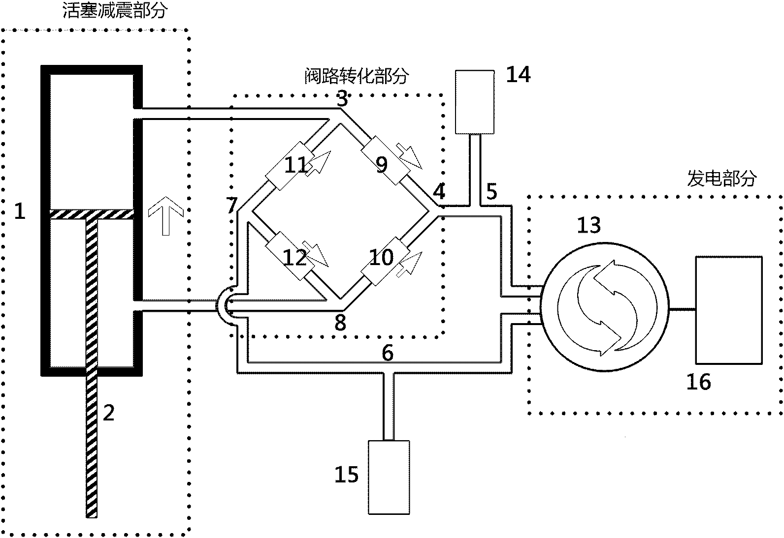
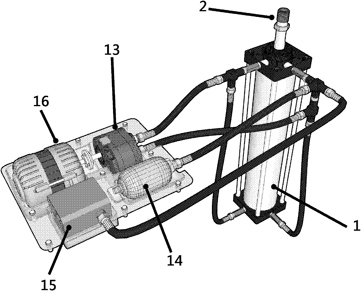
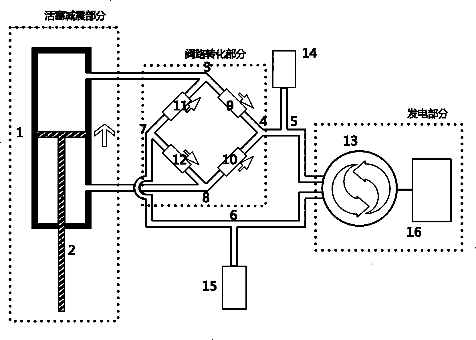
[0019] Such as figure 1 Among them, the vehicle hydraulic power generating shock absorber of the present invention includes a piston shock absorbing part, a valve circuit part and a power generating part.
[0020] The piston damping part is composed of hydraulic cylinder 1 and piston 2. The upper and lower chambers of the hydraulic cylinder each have an opening and a copper pipe is connected. When the vehicle encounters road bumps and generates vibration or starts and brakes, it will cause relative movement between the vehicle frame and the wheels. At this time, the shock absorber piston 2 will move up or down accordingly under the force of The oil is pressed out from the corresponding upper cavity outlet and sucked in from the lower cavity outlet, or hydraulic oil is pressed out from the corresponding lower cavity outlet and sucked in from the upper cavity outlet.
[0021] The bridge rectifier circuit in the valve circuit analog circuit system includes an upper cavity three-way valve 3 communicating with the upper cavity outlet of the hydraulic cylinder 1, a lower cavity three-way valve 8 communicating with the lower cavity outlet of the hydraulic cylinder 1, and a hydraulic The inlet and outlet of the motor 13 communicate with an inlet three-way valve 4 and an outlet three-way valve 7.
[0022] The upper chamber three-way valve 3 communicates with the inlet three-way valve 4 and the outlet three-way valve 7 through one-way valves 9 and 11, while the lower chamber three-way valve 8 communicates with the inlet three-way valve 4 and the inlet three-way valve through the one-way valves 10 and 12, respectively. The outlet three-way valve 7 is connected. Each valve circuit can be connected by a copper pipe.
[0023] When the piston 2 of the damping part of the piston moves upward, the upper cavity of the hydraulic cylinder 1 is a high pressure area, and the lower cavity is a low pressure area. Under the action of the pressure difference, the hydraulic oil from the outlet of the upper cavity of the hydraulic cylinder 1 is introduced into the inlet three-way valve 4 from the one-way valve 9 through the upper cavity three-way valve 3, and then enters the hydraulic motor 13 to drive it to drive a small generator 16 generates electricity, and then passes through the outlet three-way valve 7, and after the one-way valve 12, sucks into the lower cavity outlet of the hydraulic cylinder 1 from the lower cavity three-way valve 8 to complete the power generation process when the piston 2 moves upward.
[0024] When the piston 2 of the damping part of the piston descends, the lower cavity of the hydraulic cylinder 1 is a high pressure area, and the upper cavity is a low pressure area. Under the action of the pressure difference, the hydraulic oil from the outlet of the lower cavity of the hydraulic cylinder 1 is introduced into the inlet three-way valve 4 from the one-way valve 10 through the lower cavity three-way valve 8, and then enters the hydraulic motor 13 to drive it to drive a small generator 16 generates electricity, and then passes through the outlet three-way valve 7, and after the one-way valve 11, sucks into the upper cavity outlet of the hydraulic cylinder 1 from the upper cavity three-way valve 3 to complete the power generation process when the piston 2 descends.
[0025] Through this part, the flow direction of the hydraulic oil pressed from the hydraulic cylinder is controlled, so that regardless of the hydraulic oil being pressed out from the outlet of the upper cavity or the lower cavity of the hydraulic cylinder 1, the inlet and outlet of the hydraulic oil entering the hydraulic motor 13 remain unchanged, thus Ensure the one-way operation of the hydraulic motor.
[0026] The power generation part is composed of a hydraulic motor 13 and a small generator 16. This part uses hydraulic oil to push the hydraulic motor 13 to rotate to drive the small generator 16 to generate electricity.
[0027] The vehicle hydraulic power generation shock absorber of the present invention further includes an auxiliary part including an accumulator 14 and a compensation oil tank 15. The function of the accumulator 14 is to buffer, absorb vibration, reduce working noise, make the hydraulic motor rotate smoothly, and provide a stable working environment for the small generator. Since the space in the hydraulic cylinder increases when the piston moves down, and the space inside the hydraulic cylinder decreases when the piston moves up, the oil tank 15 functions to compensate and recover oil.
[0028] The invention converts the reciprocating motion of the piston rod of the hydraulic cylinder into the one-way rotary motion of the hydraulic motor through the hydraulic one-way valve, so as to drive the micro generator to charge the battery and play the role of auxiliary power supply.

PUM

no PUM

Description & Claims & Application Information

We can also present the details of the Description, Claims and Application information to help users get a comprehensive understanding of the technical details of the patent, such as background art, summary of invention, brief description of drawings, description of embodiments, and other original content. On the other hand, users can also determine the specific scope of protection of the technology through the list of claims; as well as understand the changes in the life cycle of the technology with the presentation of the patent timeline. Login to view more.

Similar technology patents

Infusion pump and control method thereof

ActiveCN105363096AAvoid pill dosesGuaranteed comfortFlexible member pumpsPressure infusionPediatricsInfusion pump
Owner:深圳影迈科技有限公司

Classification and recommendation of technical efficacy words

  • Guaranteed comfort
  • Save energy

Head mounted display

ActiveCN103487938AGuaranteed comfortRelieve visual fatigueOptical elementsHuman eyeVirtual image
Owner:CHENGDU IDEALSEE TECH

Air conditioner

Owner:HITACHI JOHNSON CONTROLS AIR CONDITIONING INC

High efficiency air conditioner condenser fan

InactiveUS20050281672A1Save energyDependable electric load reductionPropellersPump componentsPower savingAerospace engineering
Owner:UNIV OF CENT FLORIDA RES FOUND INC
Why Eureka
Try Eureka