Multi-temperature zone refrigerating system PD energy-saving control method

A refrigeration system and energy-saving control technology, applied in refrigerators, refrigeration components, refrigeration and liquefaction, etc., can solve the problems that it is difficult to achieve good results, long time for compensating temperature, high frequency of starting and stopping, and achieves low cost and extended Long service life and strong adaptability

Active Publication Date: 2011-10-12
AUCMA
View PDF0 Cites 0 Cited by
  • Summary
  • Abstract
  • Description
  • Claims
  • Application Information

AI Technical Summary

Problems solved by technology

In a multi-temperature zone refrigeration system, due to the different heat exchange characteristics of each temperature zone, the temperature change characteristics of each zone are different. For example, if a certain zone has just reached the shutdown point, another individual temperature zone will reach the start-up point but has not yet reached the start-up point. At this point, how do you need to control it? If the above situation occurs, it is generally judged before the compressor stops: Is there any temperature zone that will reach the temperature of the start-up point? Then the stepping valve switches to this area to compensate for temperature pulling until the temperature reaches the shutdown point in this area. In this way, the time for temperature compensation is generally longer, which will easily lead to low average temperature and cannot fundamentally solve the problem of high frequency of start-up and shutdown. ; The above compensation control method simply relies on temperature point control, and it is difficult to achieve good results

Method used


Image

  • Multi-temperature zone refrigerating system PD energy-saving control method
  • Multi-temperature zone refrigerating system PD energy-saving control method

Examples


Embodiment Construction

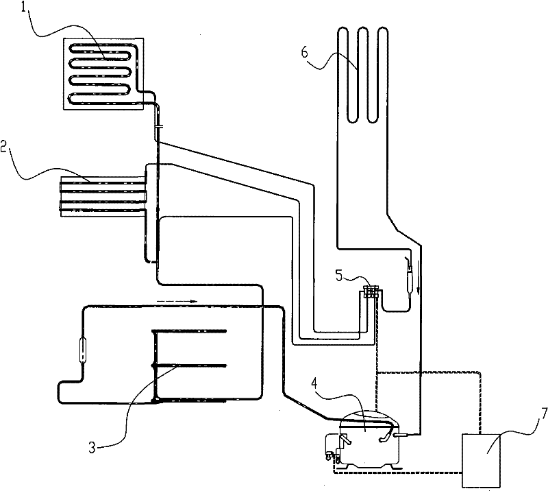
[0015] A PD energy-saving control method for a multi-temperature zone refrigeration system. A multi-temperature zone refrigeration system is selected. The multi-temperature zone refrigeration system includes a compressor, a condenser, an evaporator corresponding to two or more different temperature zones, a step valve, and a refrigeration system In the operation control part, the step valve is used to switch between the evaporators in different temperature zones to adjust the flow direction of the refrigerant; in the above operation control part, a PD single-chip microcomputer is set, and the PD single-chip microcomputer is used to pass through the temperature of each temperature zone before each compressor stops. According to the temperature rise characteristic, the downtime maintained in each temperature zone is approximately calculated. If the downtime in the variable temperature zone is shorter than the reference downtime, then the temperature pull time to be compensated is ...


PUM


Abstract

The invention discloses a multi-temperature zone refrigerating system PD energy-saving control method, which includes the following steps that: a multi-temperature zone refrigerating system, which comprises a compressor, a condenser, evaporators corresponding to more than two different temperature zones, a step valve and an operation control part, is chosen for use, and the step valve is switched between the evaporators in different temperature zones to adjust the flow direction of refrigerant; the operation control part is provided with a PD singlechip, the PD singlechip is utilized to calculate the downtime kept by each temperature zone before the compressor is shut down, the temperature-rising time to be compensated, which is kept until the reference downtime, is calculated according to the temperature reduction characteristic if the downtime of the changed temperature zone is shorter than the reference downtime, and after the step valve is switched to the changed temperature zone and operates for the temperature-rising time to be compensated, the compressor is shut down. By utilizing the PID control concept, the invention can carry out precision temperature control based on proportional derivative and increase the temperature control precision of the multi-temperature zone refrigerating system, so that energy consumption can be reduced.

Description

technical field [0001] The invention belongs to the field of integration of white goods manufacturing technology and PD single-chip microcomputer control technology, and in particular relates to an energy-saving control method for a multi-temperature zone refrigeration system such as a refrigerator or an air-conditioning system. Background technique [0002] With the development of human civilization, people's demand for life has been continuously improved, and at the same time, higher requirements have been put forward for energy conservation. At present, most of the multi-temperature zone refrigeration control systems in the domestic market are fixed-frequency control systems. Generally, a simple temperature point control method is used for temperature control. The shutdown of the compressor depends on the repeated startup and shutdown of the compressor refrigeration system to achieve the basic stability of the temperature in this temperature zone. The applicant found in ...

Claims


Application Information

Patent Timeline
Patent Type & Authority Patents(China)
IPC IPC(8): F25B49/02F25B5/00
Inventor 徐玉峰张震德孙晓庆王卫陶振雷
Owner AUCMA
Why Eureka
Try Eureka