Frame correlation processing method and system in spatial compound imaging

A space compounding and processing method technology, applied in the field of compounding, can solve the problems of different signal-to-noise ratios and time resolutions, overlapping together, disordered image information, etc., and achieve the effect of avoiding image information confusion

Active Publication Date: 2010-10-20
SHENZHEN MINDRAY BIO MEDICAL ELECTRONICS CO LTD
View PDF4 Cites 14 Cited by
  • Summary
  • Abstract
  • Description
  • Claims
  • Application Information

AI Technical Summary

Problems solved by technology

[0005] As mentioned above, the joint composite technology combined with spatial composite and frame correlation can further eliminate or reduce the influence of speckle noise, sound shadow, ultrasonic dropout, reverberation, etc. on the image, and improve the image quality. Then this simple composite implementation method There are also certain problems
Generally speaking, in the prior art, the frame correlation of ordinary B imaging is usually carried out in the spatial composite imaging mode. This will encounter two problems: first: the position of the frame correlation must be performed after the spatial composite, otherwise different angles The information is superimposed together without registration, resulting in disordered image information; second: if frame correlation is performed after spatial compounding, it may cause obvious boundaries in different areas of the image
Because under spatial compounding, the frame rate of actual update of different areas of the image after compounding is different, such as figure 1 , in the case of three-frame composite, the composite image has three areas due to the deflection of the image, where the left and right are the result of two-frame composite, and the middle is the result of three-frame composite. If the composite image is frame-correlated, left, middle, right The same correlation coefficient is used in the three areas, so the frame correlation effect in the middle area will be stronger than that in the areas on both sides, which will cause the signal-to-noise ratio and time resolution of different areas on the same image to be different. The spatial compounding of will produce visible boundaries between different regions adjacent to each other

Method used


Image

  • Frame correlation processing method and system in spatial compound imaging
  • Frame correlation processing method and system in spatial compound imaging
  • Frame correlation processing method and system in spatial compound imaging

Examples


Embodiment Construction

[0019] The specific implementation manner of the present invention will be described in detail below in conjunction with the accompanying drawings.

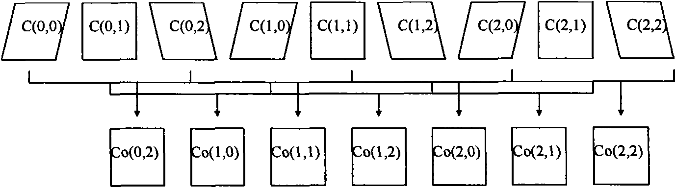
[0020] In order to effectively combine spatial compounding and frame correlation processing and improve image quality, the present invention proposes a new frame correlation processing method in spatial compound imaging, which includes the following steps:

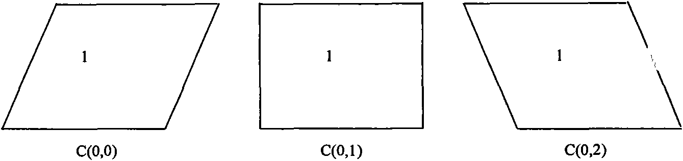
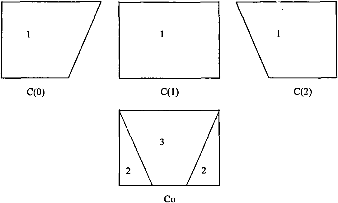
[0021] Firstly, the component images with the same deflection angle are subjected to frame correlation processing; then, the component images after the frame correlation processing are used to perform spatial composite processing to generate a composite image. The component images here may be images of the same deflection angle in adjacent deflection periods, or images of the same deflection angle in non-adjacent deflection periods.

[0022] It can be seen from the above that the present invention adds a step of frame correlation processing of frames with the same angle befor...


PUM


Abstract

The invention discloses a frame correlation processing method and a system in spatial compound imaging. The system comprises a same-angle frame correlation processor and a frame correlation coefficient calculator, wherein the same-angle frame correlation processor is used for receiving component images output by a B signal preprocessor, conducting frame correlation processing to the component images with the same deflection angle, and outputting results obtained after frame correlation processing to a spatial compound image processor; and the frame correlation coefficient calculator is used for calculating frame correlation coefficients during frame correlation processing according to the relevant parameters of a spatial compound imaging controller, and outputting results to the same-angle frame correlation processor. Aiming at the defects of a simple image processing method of using spatial compounding in combination with frame correlation, the frame correlation processing is put ahead of the spatial compounding, the same-angle frame correlation processing is adopted, the same-extent de-noising processing is conducted to different-angle information in advance before the spatial compounding and then the different-angle information is superimposed together, thereby avoiding image information disorder and not causing obvious boundaries in different areas of the images.

Description

technical field [0001] The invention relates to composite technology in an ultrasound system, in particular to a frame correlation processing method and system in spatial composite imaging. Background technique [0002] In B-mode ultrasound imaging, image quality is affected by speckle noise, acoustic shadow, ultrasonic dropout, reverberation, etc. The mechanisms of these factors are different, such as speckle noise (speckle noise) is caused by the distribution of scatterers in the imaging object and The distance from them to the probe and other factors are determined comprehensively, so that there are alternating light and dark spots on the image; due to the large reflection angle of ultrasound loss, the echo cannot be received by the probe, which is shown as discontinuity at the tissue interface on the image; The dark area, that is, the sound shadow, makes the details in it impossible to see clearly; the vertically incident ultrasonic wave forms multiple reflections betwee...

Claims


Application Information

Patent Timeline
IPC IPC(8): G06T5/00G06T5/50A61B8/00
Inventor 张羽王勇桑茂栋项峥
Owner SHENZHEN MINDRAY BIO MEDICAL ELECTRONICS CO LTD
Why Eureka
Try Eureka