Mechanism for preventing parts from cracking by inlaying insert into epoxy insulator

An epoxy insulation and insert technology, applied in insulators, electrical components, substation/switch layout details, etc., can solve problems such as cracking

Inactive Publication Date: 2010-10-20
SHANGHAI ROX ELECTRIC
View PDF0 Cites 0 Cited by
  • Summary
  • Abstract
  • Description
  • Claims
  • Application Information

AI Technical Summary

Problems solved by technology

[0005] However, if the above-mentioned structure is adopted, cracking will still occur. How to solve this problem is a matter for technicians to consider

Method used


Image

  • Mechanism for preventing parts from cracking by inlaying insert into epoxy insulator
  • Mechanism for preventing parts from cracking by inlaying insert into epoxy insulator

Examples


Embodiment Construction

[0011] Below in conjunction with accompanying drawing and specific embodiment the present invention is described in further detail:

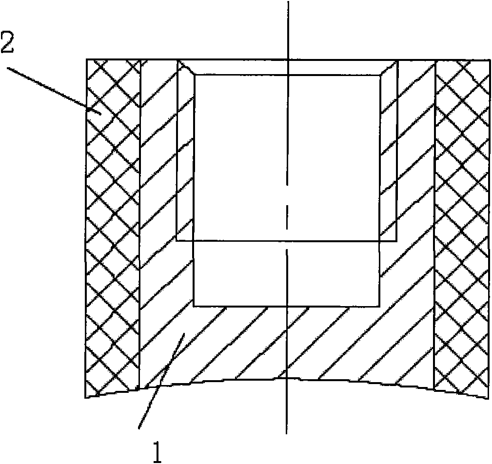
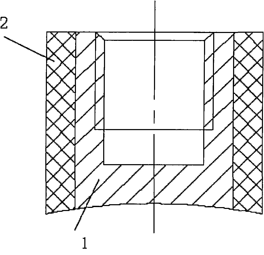
[0012] Depend on figure 1 It can be seen that the present invention includes: an insert 1 in epoxy resin; also includes: a buffer layer 2 between the epoxy resin and the insert 1;

[0013] The buffer layer 2 is semi-conductive nylon.

[0014] In the present invention, semi-conductive nylon is wrapped on the outer periphery of the metal insert, and the molding process is relatively easy; sandblasting is performed on the surface of the semi-conductive nylon before injection.

[0015] The basic principle of the present invention is: because the epoxy resin has contraction force when it is solidified in the mould, a large internal stress is generated between the metal insert and the epoxy resin. In order to relieve the stress, a buffer layer, such as semi-conductive nylon, is added between the metal insert and the epoxy resin.

[0016] Adopting t...


PUM


Abstract

The invention relates to a mechanism for preventing parts from cracking by inlaying an insert into an epoxy insulator, comprising the insert (1) in an epoxy resin and a buffer layer (2) arranged between the epoxy resin and the insert (1). The mechanism has the following beneficial effect: the buffer layer is added, thus great internal stress is generated between the metal insert and the epoxy resin so that the parts are free from cracking.

Description

technical field [0001] The invention relates to an insulator embedded part produced by epoxy resin in an APG process, in particular to the structure between the inlay and the epoxy resin. Background technique [0002] Epoxy resin is a thermosetting polymer material. The metal inserts embedded in the parts produced by this material will cause large internal stress due to uneven shrinkage during injection molding, which will cause the parts to bend or crack. [0003] In order to make the insert firmly fixed in the part and prevent the insert from rotating or pulling out in the part when it is stressed, the surface of the insert is generally made of diamond knurling, straight knurling or hexagonal, and then used for injection Molded in epoxy resin. However, due to the difference in shrinkage between the metal insert and the part, a large internal stress is generated around the insert and the part cracks. [0004] To prevent this phenomenon, in the prior art, the epoxy materia...

Claims


Application Information

Patent Timeline
Patent Type & Authority Applications(China)
IPC IPC(8): H01B17/00H01B17/38H02B1/00
Inventor 王峰费龙菲
Owner SHANGHAI ROX ELECTRIC
Why Eureka
Try Eureka