Laser driven light source

A technology of laser drive and light source, which is applied to the components of gas discharge lamps, electrical components, discharge lamps, etc., which can solve the problem of low luminous intensity of mercury, inability to control the rise of 135 mercury vapor pressure, and inability to control the full evaporation of 135 mercury, etc. problem, to achieve high output

Active Publication Date: 2010-10-20
安乃捷科技公司 +1
View PDF5 Cites 6 Cited by
  • Summary
  • Abstract
  • Description
  • Claims
  • Application Information

AI Technical Summary

Problems solved by technology

However, the existing laser-driven light source 130 removes the electrode from the bulb 135, so the mercury in the bulb 135 cannot be fully evaporated, and the mercury vapor pressure in the bulb 135 cannot be increased.
[0013] Therefore, the existing laser-driven light source 130 has the following problems: the luminous intensity of the mercury emitted to the outside of the tube bulb 135 is extremely low, and the laser light focused to the focal point in the tube bulb 135 is basically not absorbed by the mercury vapor, but emitted to the outside of the tube bulb 135. The outside of the tube bulb 135
[0014] but in Figure 13 In the laser-driven light source 130 shown, no studies have been conducted on the above-mentioned problems caused by the low mercury vapor pressure in the bulb 135
And the above-mentioned problem is not limited to when mercury is enclosed in the bulb 135 as the metal for light emission, and of course also occurs when other metals for light emission other than mercury are enclosed in the bulb 135.

Method used


Image

  • Laser driven light source
  • Laser driven light source
  • Laser driven light source

Examples


Embodiment Construction

[0051] (Laser-driven light source of the first embodiment)

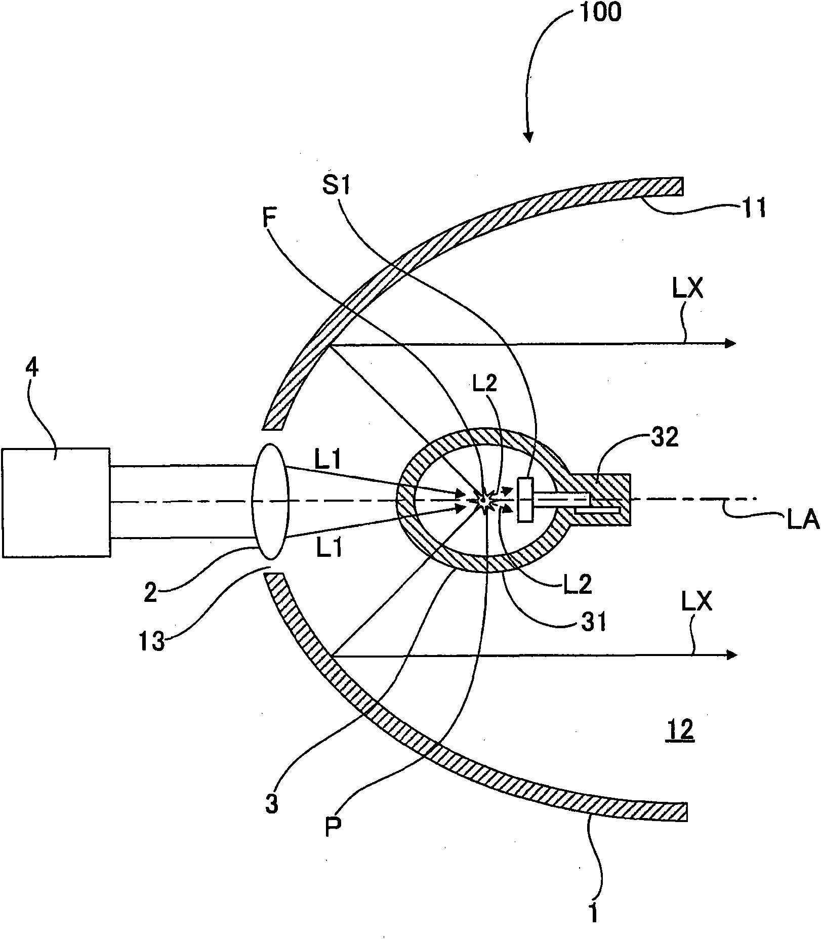
[0052] figure 1 It is a sectional view showing the basic configuration of the laser-driven light source according to the first embodiment of the present invention. The laser-driven light source of this embodiment is an electrodeless light source that does not have electrodes inside the bulb. Furthermore, the laser-driven light source of this embodiment has a light shielding member for shielding by absorbing laser light that has passed through the plasma without being absorbed by the plasma.

[0053] The laser-driven light source 100 has: a bowl-shaped concave reflector 1, which is configured around the bulb 3 and has a light exit opening 12; an optical system component 2, which condenses the laser light L1 to the focal point F in the bulb 3; The ball 3 is arranged to coincide with the focal point F of the concave mirror 1, and a discharge medium is sealed therein; the laser source 4 emits laser light to the tube 3...


PUM


Abstract

An laser driven light source comprises a bulb that encloses a discharge medium which is activated by a laser beam to generate a plasma. It is an object of the present invention to provide a shield from a laser beam, which passes through plasma generated in a bulb without being absorbed therein. A laser driven light source includes a bulb that encloses a discharge medium, wherein plasma is generated in the bulb by a laser beam focused in the bulb, and a beam shield element is provided within the bulb so as to provide a shield from the laser beam that passes through the plasma generated in the bulb.

Description

technical field [0001] The invention relates to a laser-driven light source. In particular, it relates to a laser-driven light source used as an exposure device used in the exposure process of semiconductors, liquid crystal substrates, and color filters, an image projection device for digital theaters, and a light source for optical analysis devices. Background technique [0002] In recent years, light sources used in exposure devices used in the above-mentioned exposure process, image projection devices for digital cinemas, and optical analysis devices have been required to have a long service life in addition to sufficient luminous intensity in the required wavelength region. [0003] The light source used in this field is a type in which an arc discharge is generated between electrodes in a glass tube sealed with mercury or a rare gas (xenon gas). However, since the electrodes are exposed to the arc discharge, it is difficult to avoid becoming extremely high temperature ...

Claims


Application Information

Patent Timeline
Patent Type & Authority Applications(China)
IPC IPC(8): H01J65/04
CPCH01J61/025H01J61/18H01J65/04
Inventor 住友卓安田幸夫横田利夫
Owner 安乃捷科技公司
Why Eureka
Try Eureka