
Unidirectional transmission method based on optical fiber multi-way coupling

A unidirectional transmission, optical fiber technology, applied in the field of data security transmission, can solve the problems of security relying on the reliability of hardware logic, the unidirectionality of the isolation card is not guaranteed by a physical mechanism, and it is not easy to use.

Inactive Publication Date: 2012-12-12
NAT UNIV OF DEFENSE TECH
View PDF0 Cites 0 Cited by
  • Summary
  • Abstract
  • Description
  • Claims
  • Application Information

AI Technical Summary

Problems solved by technology

The main disadvantage of the one-way transmission method based on the U disk is that there is no one-way guarantee on the physical mechanism, the security depends on the reliability of the hardware logic, and the cost of use is high (not easy for most people to use)
The one-way transmission method based on the hardware isolation card uses the network to transmit information from the low-density level to the high-density level, and the one-way performance is guaranteed through the hardware isolation card in the middle. Its main disadvantages are similar to the one-way transmission technology based on the U disk. tropism is not guaranteed by a physical mechanism
The unidirectional transmission technology based on single-channel optical fiber utilizes the one-way irreversible physical mechanism of photon movement in the optical fiber channel to ensure security. Its main disadvantage is that there is only a single unidirectional optical fiber channel, and the overall performance of the system is limited by the maximum bandwidth of a single optical fiber.

Method used


Image

  • Unidirectional transmission method based on optical fiber multi-way coupling
  • Unidirectional transmission method based on optical fiber multi-way coupling
  • Unidirectional transmission method based on optical fiber multi-way coupling

Examples


Embodiment Construction

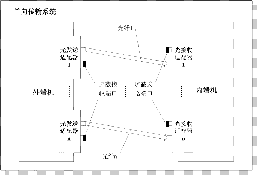
[0060] figure 1 It is a logical structure diagram of the one-way transmission system constructed in the first step of the present invention; the one-way transmission system is composed of an external terminal, an internal terminal and n one-way transmission channels, where n is a positive integer. The external machine is a low-density computer device that can be connected to a low-density network. It sends the data that requires one-way transmission to n one-way transmission channels; the one-way transmission channel sends data to the internal network in a physically irreversible manner. Terminal machine; the internal terminal is a high-density computer device that can be connected to a high-density network and can restore and process the received one-way data.

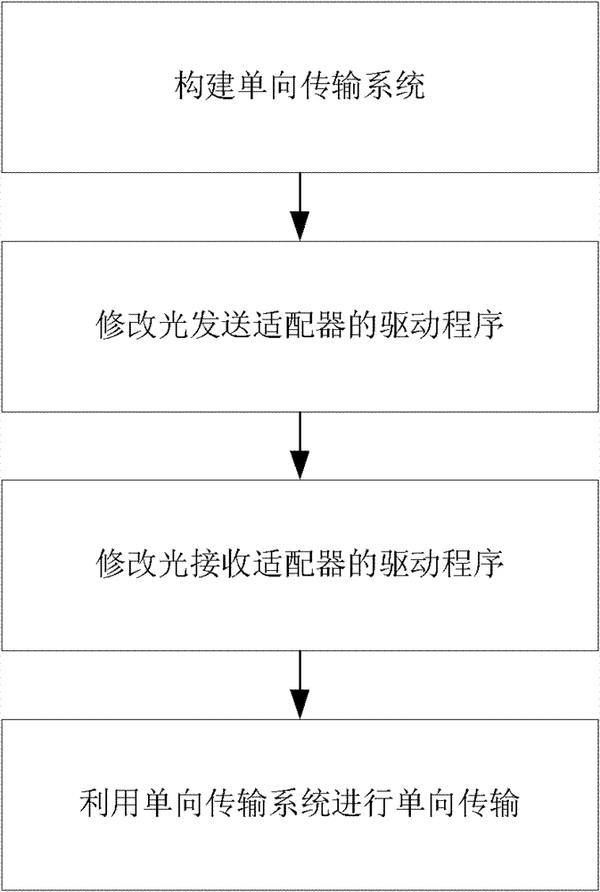
[0061] figure 2 Is the overall flow chart of the present invention; The present invention comprises following four steps: the first step, constructs such as figure 1 The one-way transmission system shown; the secon...


PUM


Abstract

The invention discloses a unidirectional transmission method based on optical fiber multi-way coupling, aiming at providing a method which is used for transmitting data from low-dense network into a high-dense network in a unidirectional way, and is high in speed, reliable, safe and expandable in unidirectional transmission speed. The method has the technical scheme that first, a unidirectional transmission system formed by an outer terminal machine, an inner terminal machine and a number of unidirectional transmission channels is built; then, the driving program of an optical transmitting adapter is modified, and the transmitting end program can be obtained; the driving program of an optical receiving adapter is modified, and the receiving end program can be obtained; and finally, unidirectional transmission is carried out by the unidirectional transmission system. The method can be used for building the unidirectional transmission channels which can guarantee pure unidirectional property in the aspect of physics with lower cost, thus ensuring information not to flow into a low-dense system from a high-dense system; and due to the multi-way coupling way, the speed of the unidirectional channels can be flexibly increased in a multifold way.

Description

technical field [0001] The invention relates to the field of data security transmission, in particular to a method for unidirectionally transmitting data from a low-density network to a high-density network. Background technique [0002] A large number of government agencies, military units, and companies have multiple networks with different security levels. How to safely and reliably realize information exchange between networks with different security levels is an important problem that needs to be solved urgently in my country's informatization construction. At present, one-way transmission of data from a low-density network to a high-density network is mainly through burning CDs. In addition to being inconvenient to use, it also causes a lot of waste of CDs and has potential safety hazards (the CD itself cannot guarantee that data can only be transferred from a low-density system in one direction) High-secret system flows, so it may become a carrier of leaks). [0003...

Claims


Application Information

Patent Timeline
Patent Type & Authority Patents(China)
IPC IPC(8): H04B10/12H04L29/06H04B10/25
Inventor 唐勇陈曙晖黄高平苏金树杨岳湘王勇军钟求喜赵国鸿宣蕾
Owner NAT UNIV OF DEFENSE TECH
Learn More