
Optical signal receiving method, optical signal receiving device and optical transmission system

An optical signal and signal technology, applied in the field of optical communication, can solve the problems of reduced receiver reception performance, wrong judgment, large phase error, etc., and achieve the effect of reducing the bit error rate and compensating for the phase error

Active Publication Date: 2010-10-20
HUAWEI TECH CO LTD +1
View PDF3 Cites 20 Cited by
  • Summary
  • Abstract
  • Description
  • Claims
  • Application Information

AI Technical Summary

Problems solved by technology

[0005] 1. The existing technology actually uses the phase error calculated by the type I constellation point to compensate the phase of the type II constellation point. There is only judgment for the phase of the type I constellation point without compensation, and when there is a long-term continuous When the type II constellation point is used, the residual phase error is very large, resulting in a wrong judgment when judging the phase of the type II constellation point;
[0006] 2. The existing technology does not compensate for the nonlinear phase shift generated during the transmission process, resulting in a significant reduction in the receiving performance of the receiver, such as: the bit error rate of the signal received by the receiver will be very high

Method used


Image

  • Optical signal receiving method, optical signal receiving device and optical transmission system
  • Optical signal receiving method, optical signal receiving device and optical transmission system
  • Optical signal receiving method, optical signal receiving device and optical transmission system

Examples


Embodiment Construction

[0040] The following will clearly and completely describe the technical solutions in the embodiments of the present invention with reference to the accompanying drawings in the embodiments of the present invention. Obviously, the described embodiments are only some, not all, embodiments of the present invention. Based on the embodiments of the present invention, all other embodiments obtained by persons of ordinary skill in the art without making creative efforts belong to the protection scope of the present invention.

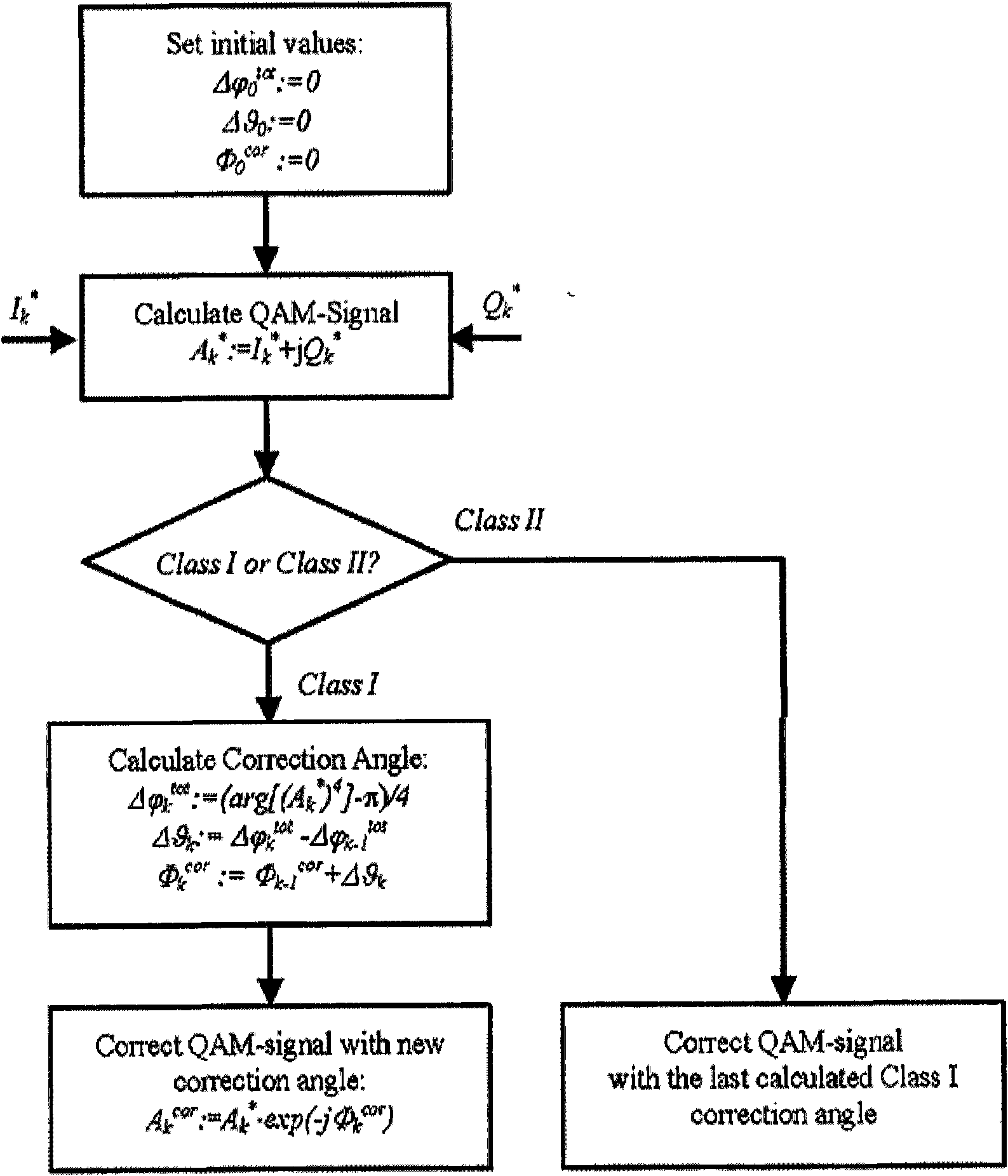
[0041] Embodiment 1 of the present invention provides a method for receiving an optical signal, which is used to receive a square 16QAM optical signal sent by the transmitting end. The flow chart of the method is as follows image 3 shown.

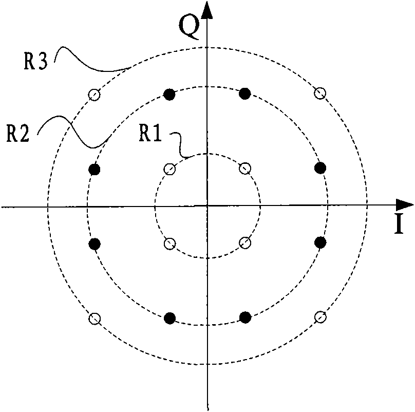
[0042] The 16QAM optical signal is obtained by modulating the square 16QAM signal onto the optical carrier at the transmitting end. The 16QAM signal set is described by a constellation diagram, and the corresponding conste...


PUM


Abstract

The invention relates to an optical signal receiving method, an optical signal receiving device and an optical transmission system; the method comprises the following steps: receiving a 16QAM optical signal and local oscillator light, carrying out coherent detection to the signal and the light to obtain a 16QAM signal; according to the nonlinear phase shift factor and the drift phase error make-up corresponding to a previous 16QAM signal, pre-compensating for the phase of a current 16QAM signal, calculating the nonlinear phase shift factor and the shift phase error corresponding to the current 16QAM and takes the same as the nonlinear phase shift factor and the shift phase error required by compensating for a next 16QAM signal. The realization of the embodiment of the invention not only can effectively compensate for the shift phase error caused by frequency shift and phase shift between optical carrier and the local oscillator light, but also can compensate for the nonlinear phase shift of the 16QAM optical signal when transmitted in an optical fiber caused by nonlinear effect, thereby greatly reducing the error rate of the system and not producing format effect.

Description

technical field [0001] The invention relates to the technical field of optical communication, in particular to an optical signal receiving method, an optical signal receiving device and an optical transmission system. Background technique [0002] At present, the combination of high-order optical modulation technology and coherent detection technology can improve the spectral efficiency of optical transmission and improve the transmission capacity of existing systems, which has attracted people's attention. In recent years, the rapid development of electronic technology and high-speed digital signal processing (DSP) technology has made coherent optical communication technology more and more perfect. Digital signal processing technology can be used to equalize and compensate the received signal in the electrical domain. However, some practical factors hinder the development of optical communication to higher speed and higher order. For example, in the 16QAM transmission syst...

Claims


Application Information

Patent Timeline
IPC IPC(8): H04B10/148H04J14/00H04B10/60H04L27/38
Inventor 卢媛媛苏翼凯熊前进
Owner HUAWEI TECH CO LTD
Learn More