Wound dressing

A wound and wound contact layer technology, applied in dressings, viscous dressings, wound drainage devices, etc., can solve problems such as time-consuming, rupture, and cross-infection of users, and achieve the effect of reducing the risk of infection

Active Publication Date: 2010-10-20
SMITH & NEPHEW INC
View PDF7 Cites 342 Cited by
  • Summary
  • Abstract
  • Description
  • Claims
  • Application Information

AI Technical Summary

Problems solved by technology

It should be recognized that such exudate removal and pump removal can be time consuming and can lead to cros

Method used


Image

  • Wound dressing
  • Wound dressing
  • Wound dressing

Examples


Embodiment Construction

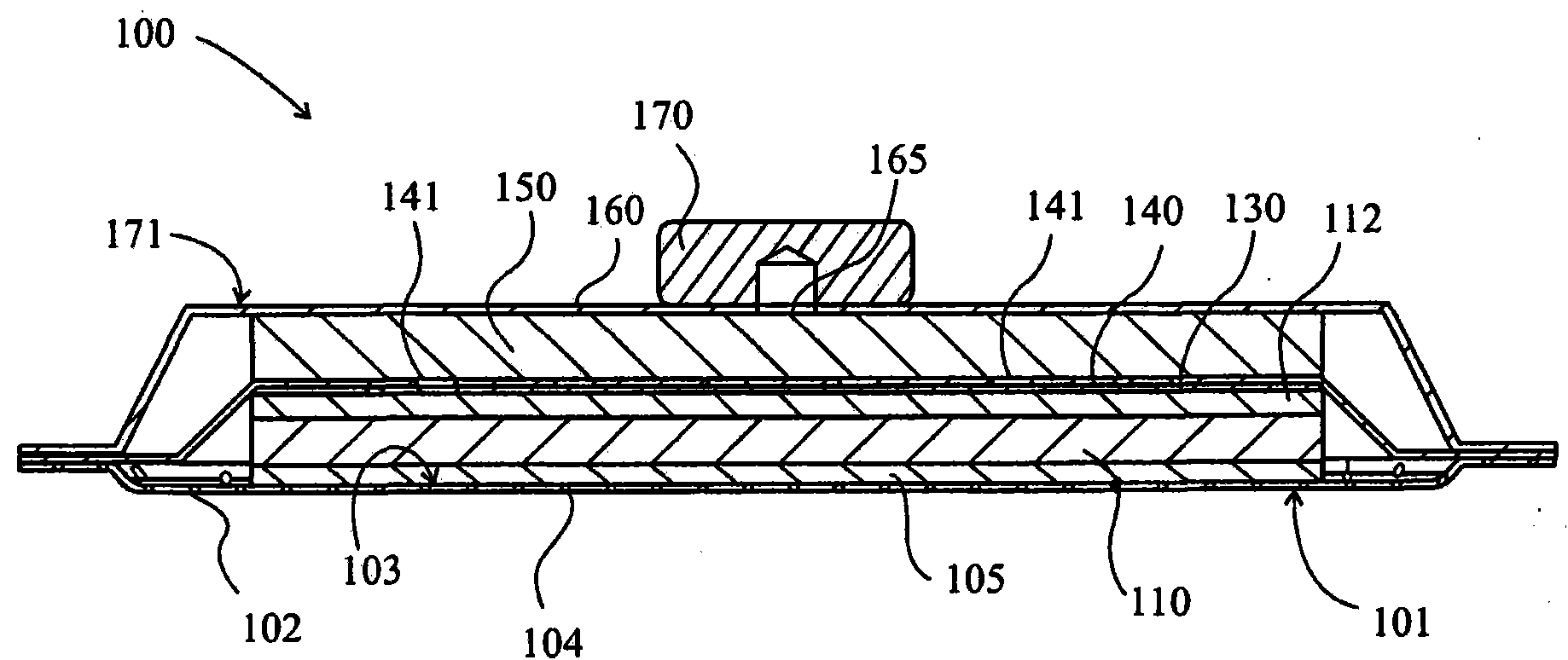
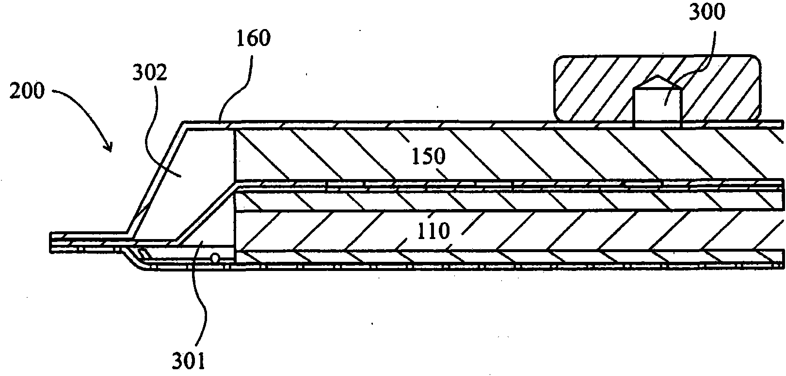
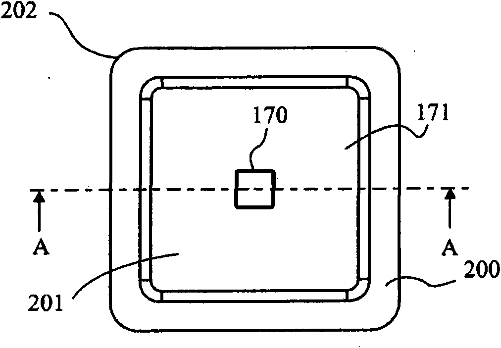
[0035] figure 1 A cross-sectional view through a wound dressing 100 according to an embodiment of the invention is illustrated. A top view of wound dressing 100 is illustrated at figure 2 , where line A-A indicates the figure 1 The location of the section shown in . It should be understood that figure 1 A generalized schematic diagram of device 100 is illustrated. It should be understood that embodiments of the present invention are generally applicable to body partial negative pressure (TNP) systems. In short, negative pressure wound therapy aids in the closure of many forms of "hard-to-heal" wounds by reducing tissue edema, promoting blood flow and particulate tissue formation, removing excess exudate, and reducing bacterial growth (and risk of infection). heal. In addition, the treatment results in less wound disturbance, resulting in faster healing.

[0036] Wound dressing 100 may be positioned over a wound site to be treated. The dressing 100 forms a sealed cavit...


PUM


Abstract

A method and apparatus are disclosed for dressing a wound. The apparatus comprises an absorbent layer for absorbing wound exudate, a liquid impermeable, gas permeable filter layer over the absorbent layer, a cover layer comprising at least one orifice and a first liquid and gas permeable transmission layer underlying the absorbent layer. The transmission layer is in fluid communication with the filter layer.

Description

technical field [0001] The present invention relates to methods and devices for dressing wounds and methods for manufacturing wound dressings. In particular, but not exclusively, the present invention relates to a wound dressing useful during body topical negative pressure (TNP) therapy, wherein the wound dressing itself acts as a waste tank to collect and store the wound removed from the wound site exudate. Background technique [0002] For topical negative pressure (TNP) therapy applied to wounds and other therapeutic procedures aimed at enhancing the effects of TNP therapy, there is a number of available prior art related to the provision of devices and methods of their use. Examples of such prior art include those listed and briefly described below. [0003] By reducing tissue edema, promoting blood flow and micronization of tissue, and removing excess exudate, TNP therapy aids in wound closure and healing and may reduce bacterial growth and wound infection. Moreover,...

Claims


Application Information

Patent Timeline
IPC IPC(8): A61F13/02A61F13/00A61M1/00
CPCA61F2013/00536A61F13/02A61M1/009A61F2013/0028A61M27/00A61M1/0088A61F13/00068A61M1/962A61M1/985A61M1/912A61M1/915A61F13/0206A61F13/0209A61F13/0226A61F13/0216A61M2205/7536A61F13/022A61M1/90A61F13/0253A61F13/00063A61F13/025A61F2013/00246
Inventor E·Y·哈特威尔
Owner SMITH & NEPHEW INC
Why Eureka
Try Eureka