Punch unit

A technology for discharging holes and punching dies, applied in metal processing, etc., can solve problems such as difficulty in core alignment, increased cost, and increased number of parts, and achieve the effects of improved perforation quality, compact structure, and increased rigidity

Inactive Publication Date: 2010-10-20
DAIDO KOGYO CO LTD
View PDF2 Cites 3 Cited by
  • Summary
  • Abstract
  • Description
  • Claims
  • Application Information

AI Technical Summary

Problems solved by technology

[0004] The punch shaft and the die shaft of the punching unit are respectively stored in the punch frame and the die frame which are integrally formed parts, so that the number of parts can be reduced compared to a structure in which a plurality of plate-shaped parts are assembled to form the punch frame and the die frame And reduce the assembly man-hours, but it is difficult to align the core, and it is difficult to adjust to a suitable engagement gap
[0005] In addition, it is difficult to sufficiently ensure the rigidity of the above-mentioned punch shaft and die shaft according to the restriction on the external dimensions of the punching unit, and unevenness of the engagement gap may occur due to the thickness of the sheet, thereby degrading the quality of the punched hole.
In addition, since it is necessary to have a punch frame and a die frame with closed end faces, this increases the number of parts and takes assembly time, thus becoming a cause of cost increase
[0006] Furthermore, if the chippings taken out by the discharge rod are allowed to fall naturally and be discharged from the chip discharge hole, the chippings cannot be fully discharged.

Method used


Image

  • Punch unit
  • Punch unit
  • Punch unit

Examples


Embodiment approach 1

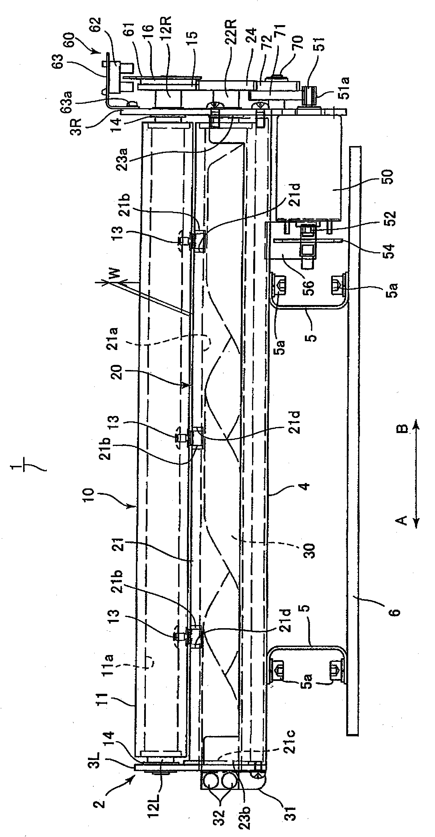
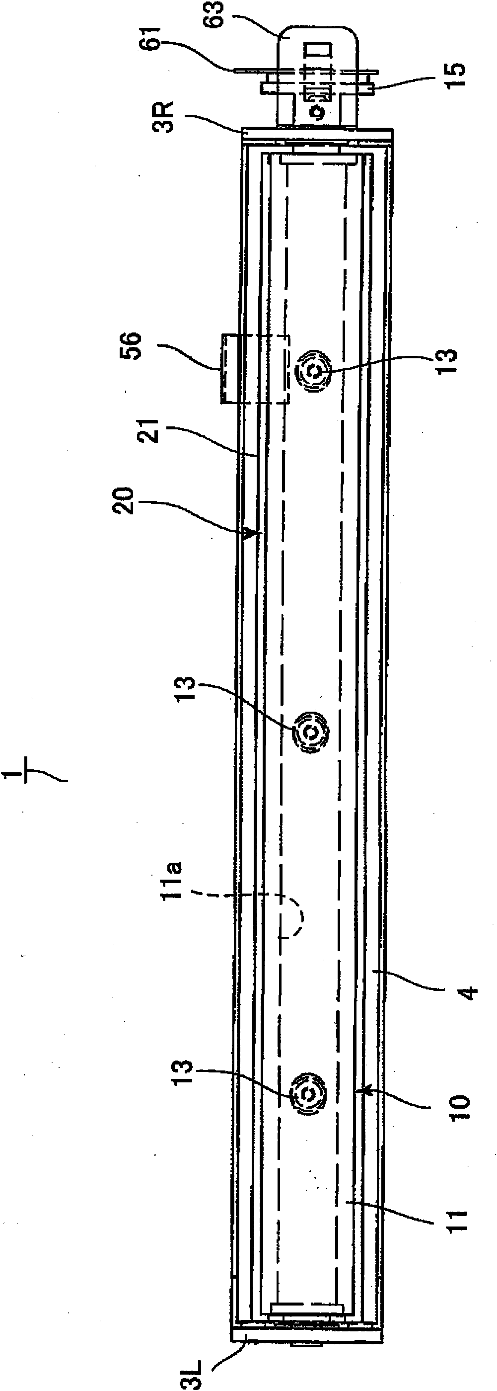
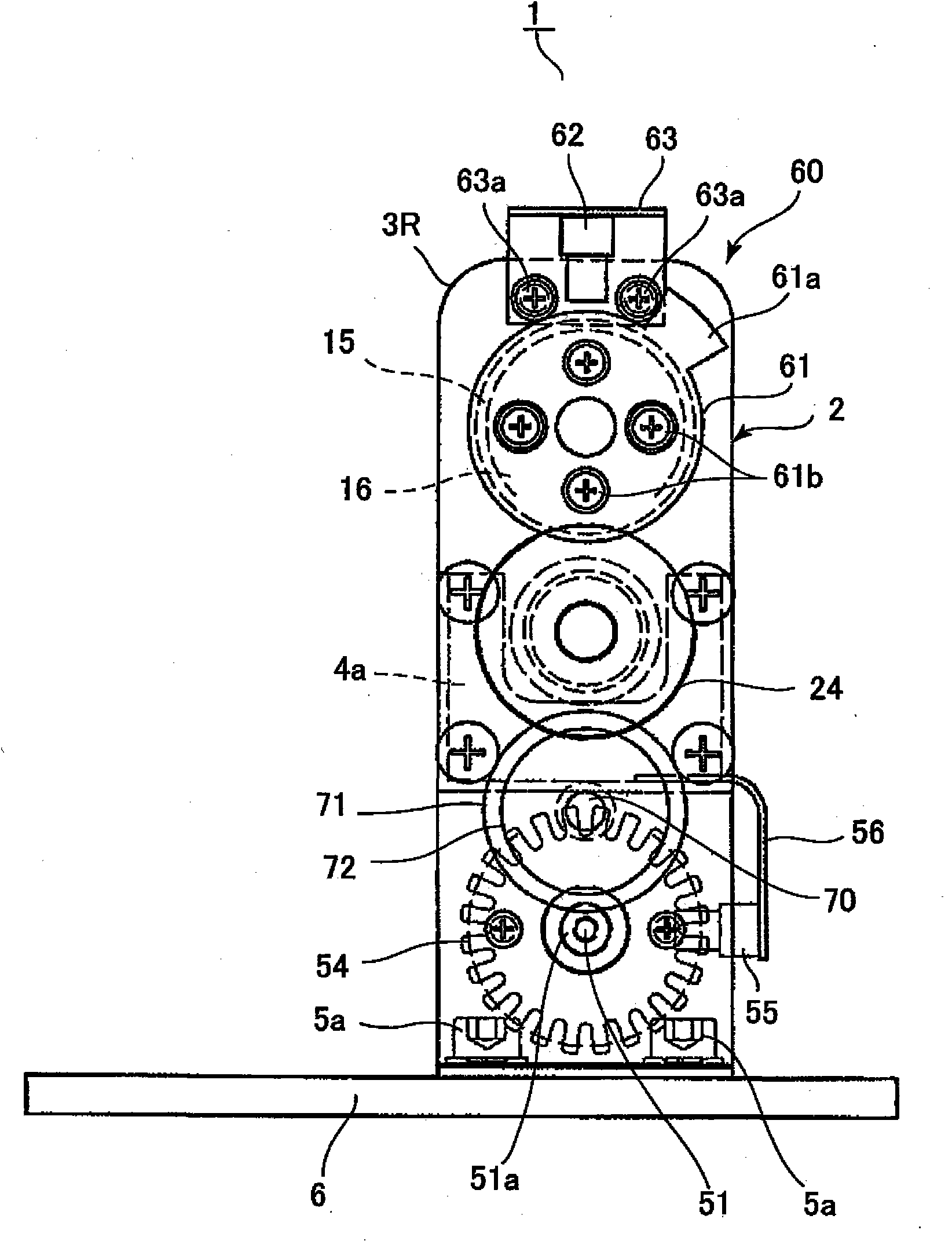
[0033] Perforation unit 1, such as figure 1 image 3 As shown, there is a base 6 fixed to the frame of an image forming apparatus (including a post-processing device) such as a printer, and a bottom plate 4 is fixed to the base 6 with bolts 5 a via a plurality of leg portions 5 . Left and right side plates 3L, 3R are fixed to left and right ends of the bottom plate 4, and the frame 2 is constituted by the above-mentioned integrated bottom plate 4 and side plates 3L, 3R. In addition, the punch shaft 10 and the die shaft 20 are arranged in parallel on the side plates 3L, 3R so that both ends thereof are rotatably supported, and the punch shaft 10 and the die shaft 20 together with the frame 2 form holes. Construction part (strength part) of unit 1. In addition, the punch shaft 10 and the die shaft 20 are supported by the side plates 3L, 3R with a predetermined gap W forming an engagement gap through which a sheet passes.

[0034] The above-mentioned punch shaft 10 is constit...

Embodiment approach 2

[0053] Figure 4 and Figure 7 (b) shows the punching unit according to Embodiment 2 of the present invention. In this embodiment, the chip discharge screw plate 30 fixed in the first embodiment has a structure in which a round bar is made into a helical blade, and is integrally arranged in the hollow portion 21a of the die shaft 20, and the configurations different from those in the first embodiment will be described below. part.

[0054] Such as Figure 4 and Figure 7 As shown in (b), the chip discharge screw rod 80 (guide, screw structure) as the hole chip conveying body is made of a round rod as a helical blade, and is fitted into the hollow part 21a of the die shaft main body 21 to be integrally installed. . Therefore, when the die shaft 20 rotates, the chip discharge screw 80 rotates integrally with the inner peripheral surface of the hollow portion 21a of the die shaft main body 21, and the hole chips flow along the edge of the chip discharge screw 80 based on the...

Embodiment approach 3

[0059] Figure 5 , Figure 6 as well as Figure 7 (c) is a diagram showing a punching unit according to Embodiment 3 of the present invention. In this embodiment, the fixed chip discharge spiral plate 30 in the first embodiment is changed to a coil-shaped member, and the coil member is driven by a motor. The parts different from the configuration of the first embodiment will be described below.

[0060] Such as Figure 5 , Figure 6 as well as Figure 7 As shown in (c), the chip discharge coil (guide, screw member) 90 as the hole chip conveying body is formed by winding a metal wire or a plastic flexible member into a cylindrical shape, and is installed on one end thereof. There is a drive gear 94 . The chip ejection coil 90 from the Figure 5 The direction of arrow A indicated by arrow A is arranged in the hollow portion 21a of the die shaft main body 21 toward the direction B, and the drive gear 94 is rotatably supported on the side of the left side plate 3L.

[0061...


PUM


Abstract

A punch shaft (10) and a die shaft (20) are supported by side plates (3L, 3R) in a parallel and vertically spaced apart relationship, and the punch shaft (10) and the die shaft (20) form a structural member (strength retaining member). The die shaft (20) has a die shaft body (21) formed in a hollow circular cylindrical shape. Dies (21b) corresponding to punches (13) of the punch shaft (10) are mounted on the outer periphery of the die shaft body (21) by being fitted in die holes (21d) penetrating through up to a hollow (21a) in the die shaft (20). A waste discharge screw plate (30) fixed to the side plate (3R) is placed in the hollow (21a) in the die shaft (20). As the die shaft (20) rotates, punch waste is transferred along a sloped surface of the waste discharge screw plate (30) and discharged from a punch waste discharge hole (21c). The punch unit can be easily adjusted, can form high quality holes in a sheet, and can reliably discharge punch waste.

Description

technical field [0001] The present invention relates to a punching unit installed in an image forming apparatus such as a copying machine or a printer, and perforating a recording sheet or the like after image formation is completed. Background technique [0002] Conventionally, there has been proposed a piercing unit in which a punch of the punch shaft is engaged with a die of the die shaft by rotating a punch shaft and a die shaft that are arranged in parallel with each other and have a plurality of punches and dies. Perforations are formed in the sheet (for example, refer to JP-A-2000-301492 and JP-A-2000-301494). [0003] The punch shaft and the die shaft are respectively housed in a cylindrical integrally formed punch frame and die frame having closed end faces, and the punch frame and the die frame are structural members (strength members) of the punching unit. In addition, a chip discharge hole is provided on the die frame at a position corresponding to the die, and ...

Claims


Application Information

Patent Timeline
Patent Type & Authority Applications(China)
IPC IPC(8): B26D7/18B26F1/08
CPCB26D7/18B26F1/10B26D5/32Y10T83/222Y10T83/7809Y10T83/9387
Inventor 西村和夫间嶋利幸市川惠美石井进
Owner DAIDO KOGYO CO LTD
Why Eureka
Try Eureka