Punch unit

一种穿设、排出孔的技术,应用在图像形成装置领域,能够解决孔屑不能被充分地排出等问题,达到提高穿孔品质、防止堵塞、提高刚性的效果

Inactive Publication Date: 2013-02-13
DAIDO KOGYO CO LTD
View PDF2 Cites 0 Cited by
  • Summary
  • Abstract
  • Description
  • Claims
  • Application Information

AI Technical Summary

Problems solved by technology

[0006] Furthermore, if the chippings taken out by the discharge rod are allowed to fall naturally and be discharged from the chip discharge hole, the chippings cannot be fully discharged.

Method used


Image

  • Punch unit
  • Punch unit
  • Punch unit

Examples


Embodiment approach 1

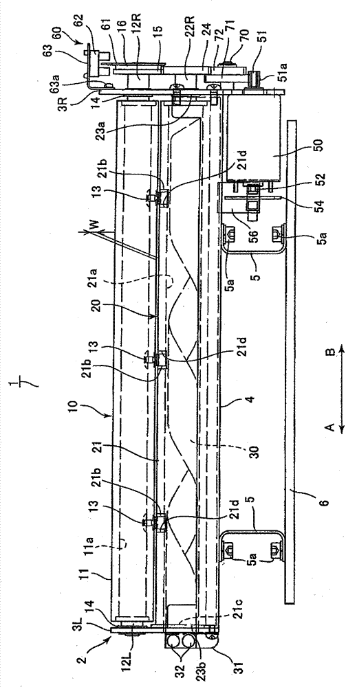
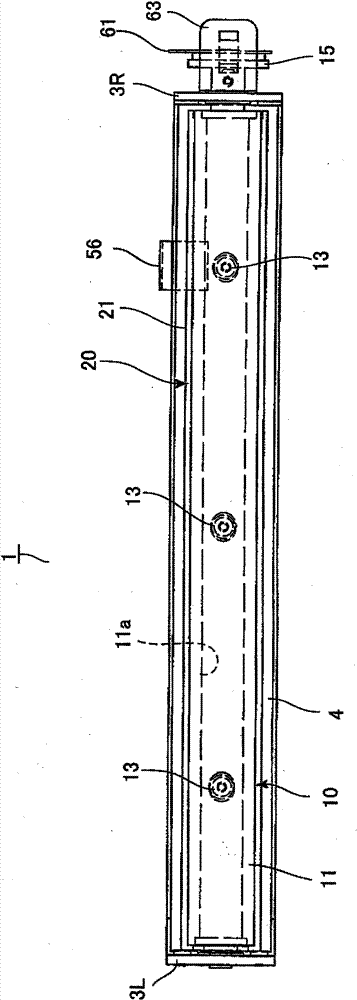
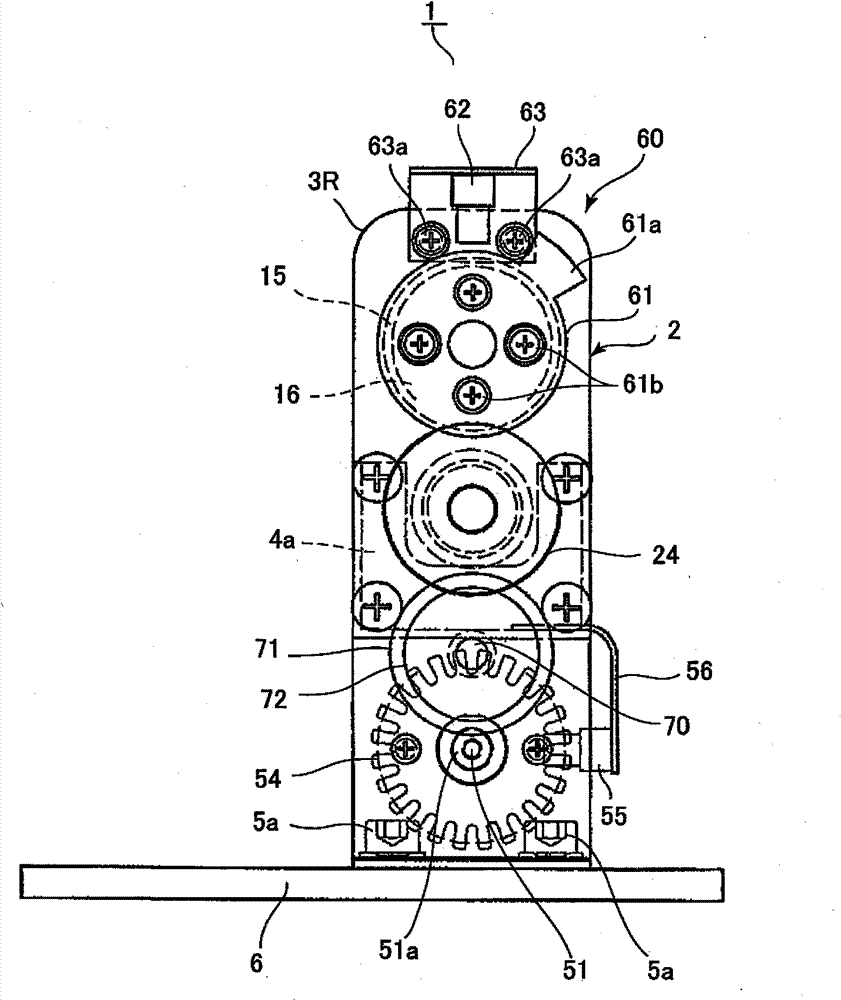
[0033] Perforation unit 1, such as figure 1 image 3 As shown, there is a base 6 fixed to the frame of an image forming apparatus (including a post-processing device) such as a printer, and a bottom plate 4 is fixed to the base 6 with bolts 5 a via a plurality of leg portions 5 . Left and right side plates 3L, 3R are fixed to left and right ends of the bottom plate 4, and the frame 2 is constituted by the above-mentioned integrated bottom plate 4 and side plates 3L, 3R. In addition, the punch shaft 10 and the die shaft 20 are arranged in parallel on the side plates 3L, 3R so that both ends thereof are rotatably supported, and the punch shaft 10 and the die shaft 20 together with the frame 2 form holes. Construction part (strength part) of unit 1. In addition, the punch shaft 10 and the die shaft 20 are supported by the side plates 3L, 3R with a predetermined gap W forming an engagement gap through which a sheet passes.

[0034] The above-mentioned punch shaft 10 is constit...

Embodiment approach 2

[0053] Figure 4 and Figure 7 (b) shows the punching unit according to Embodiment 2 of the present invention. In this embodiment, the chip discharge screw plate 30 fixed in the first embodiment has a structure in which a round bar is made into a helical blade, and is integrally arranged in the hollow portion 21a of the die shaft 20, and the configurations different from those in the first embodiment will be described below. part.

[0054] like Figure 4 and Figure 7 As shown in (b), the chip discharge screw rod 80 (guide, screw structure) as the hole chip conveying body is made of a round rod as a helical blade, and is fitted into the hollow part 21a of the die shaft main body 21 to be integrally installed. . Therefore, when the die shaft 20 rotates, the chip discharge screw 80 rotates integrally with the inner peripheral surface of the hollow portion 21a of the die shaft main body 21, and the hole chips flow along the edge of the chip discharge screw 80 based on the pr...

Embodiment approach 3

[0059] Figure 5 , Image 6 as well as Figure 7 (c) is a diagram showing a punching unit according to Embodiment 3 of the present invention. In this embodiment, the fixed chip discharge spiral plate 30 in the first embodiment is changed to a coil-shaped member, and the coil member is driven by a motor. The parts different from the configuration of the first embodiment will be described below.

[0060] like Figure 5 , Image 6 as well as Figure 7 As shown in (c), the chip discharge coil (guide, screw member) 90 as the hole chip conveying body is formed by winding a metal wire or a plastic flexible member into a cylindrical shape, and is installed on one end thereof. There is a drive gear 94 . The chip ejection coil 90 from the Figure 5 Arrow A direction of , is disposed in the hollow portion 21a of the die shaft main body 21 toward the direction B, and the drive gear 94 is rotatably supported on the side of the left side plate 3L.

[0061] In addition, a bracket 93 ...


PUM


Abstract

There is provided a punching unit that is readily adjusted, is capable of always punching high quality holes through sheets and is steadily capable of discharging punch chips. A punch shaft and a die shaft are disposed vertically in parallel between side plates and these very punch shaft and the die shaft compose structural members (reinforcing members) of the punching unit. The die shaft has a die shaft body formed into a hollow cylinder and is provided with dies that correspond to the punches of the punch shaft at an outer peripheral surface thereof while fitting into die holes penetrating to the hollow section. A chip discharging screw plate fixed to the right side plate is disposed in the hollow section of the die shaft. Punch chips are transported along slopes of the chip discharging screw plate and discharged out of an opening when the die shaft rotates.

Description

technical field [0001] The present invention relates to a punching unit installed in an image forming apparatus such as a copying machine or a printer, and perforating a recording sheet or the like after image formation is completed. Background technique [0002] Conventionally, there has been proposed a piercing unit in which a punch of the punch shaft is engaged with a die of the die shaft by rotating a punch shaft and a die shaft that are arranged in parallel with each other and have a plurality of punches and dies. Perforations are formed in the sheet (for example, refer to JP-A-2000-301492 and JP-A-2000-301494). [0003] The punch shaft and the die shaft are respectively housed in a cylindrical integrally formed punch frame and die frame having closed end faces, and the punch frame and the die frame are structural members (strength members) of the punching unit. In addition, a chip discharge hole is provided on the die frame at a position corresponding to the die, and ...

Claims


Application Information

Patent Timeline
Patent Type & Authority Patents(China)
IPC IPC(8): B26D7/18B26F1/08
CPCB26D7/18B26D5/32B26F1/10Y10T83/222Y10T83/7809Y10T83/9387
Inventor 西村和夫间嶋利幸市川惠美石井进
Owner DAIDO KOGYO CO LTD
Why Eureka
Try Eureka