Bidirectional servo feeding machine

A servo feeding and feeding technology, applied in the field of two-way servo feeder, can solve problems such as difficult to use, large material waste, large area, etc., and achieve the effect of improving utilization rate, convenient adjustment and reducing cost

Inactive Publication Date: 2010-10-27
LEN SEIKI SHENZHEN
View PDF6 Cites 7 Cited by
  • Summary
  • Abstract
  • Description
  • Claims
  • Application Information

AI Technical Summary

Problems solved by technology

For the stamping products of round parts, this kind of feeder has a large waste of material
Since the stamped parts are mostly round (such as the lower round cake or round parts), the width of the material used for stamping suc

Method used


Image

  • Bidirectional servo feeding machine
  • Bidirectional servo feeding machine
  • Bidirectional servo feeding machine

Examples


Embodiment Construction

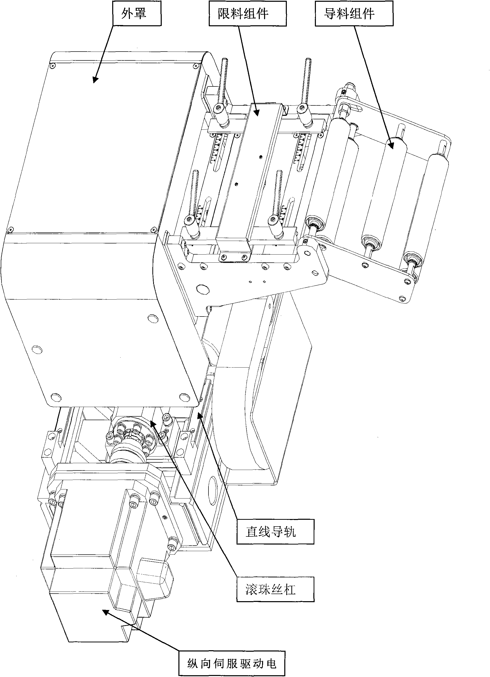
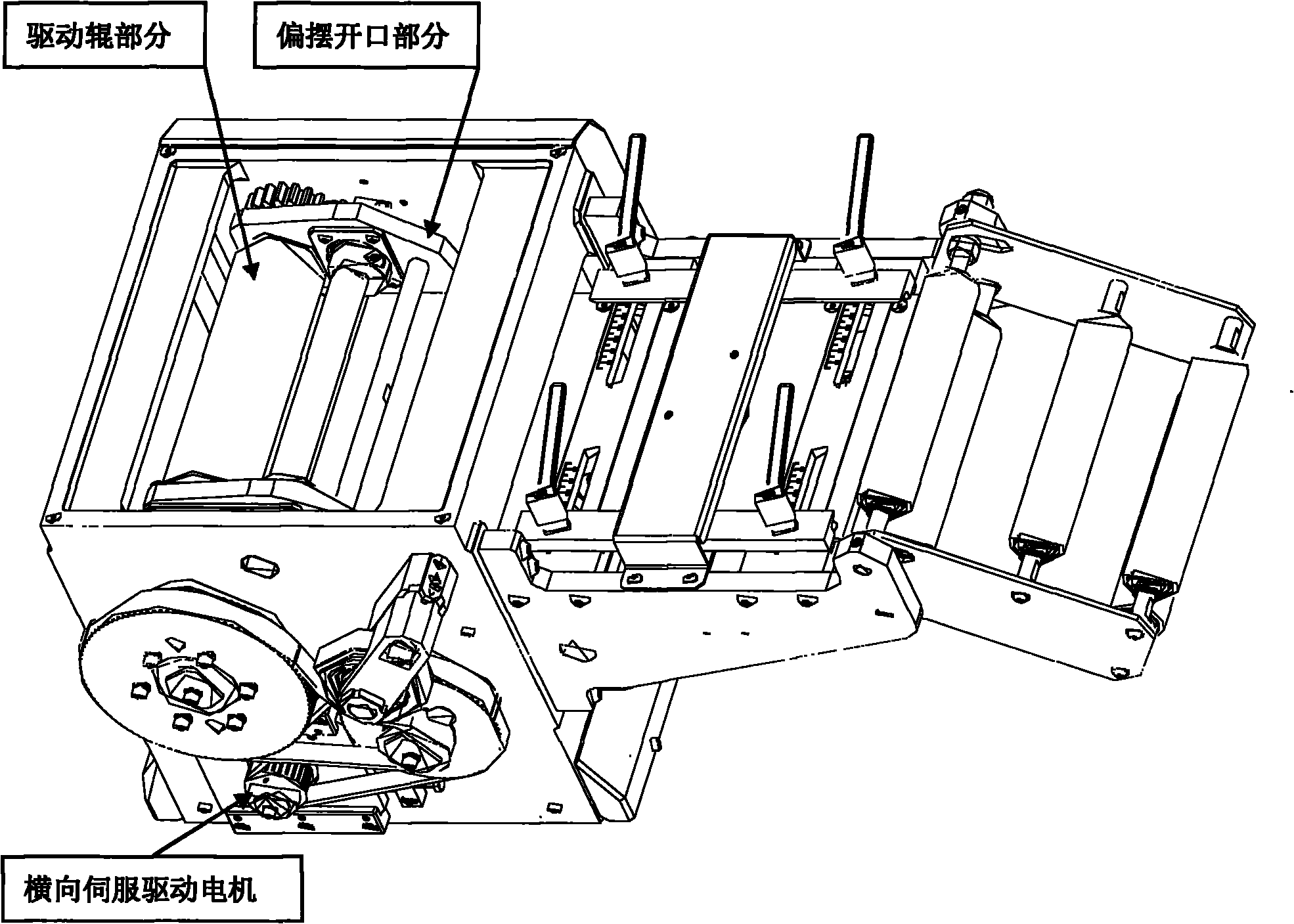
[0017] Such as figure 2 , image 3 Shown is a schematic diagram of the appearance of the bidirectional servo feeder of the present invention. The horizontal feeding mechanism drives the two-stage deceleration synchronous pulley 2, the lower feeding roller 3, and the upper feeding roller 4 to feed materials forward through the lateral servo drive motor 1. Wherein the lower feeding roller 3 is a driving roller, and the upper feeding roller 4 is a driven roller, which transmits power by meshing with the gear 5 at the shaft end of the driving roller, and the synchronous belt 6 is provided with a tensioning device 7 . The cylinder 8 can drive the swing arm 9 and the upper feeding roller 4 to swing around the rotating shaft 10 through the hinged connection. When feeding, the upper feeding roller 4 and the lower feeding roller 3 clamp the coiled material between the upper and lower rollers in close contact to ensure the dimensional accuracy of the feeding. Adjusting the pressure o...


PUM


Abstract

The invention provides a bidirectional servo feeding machine which is matched with a punching machine in punching industry. The feeding machine is connected with the punching machine through an electric appliance control signal to automatically feed punching steel coils both in a transverse direction (the advancing direction of the coils) and a longitudinal direction (perpendicular to the advancing direction of the coils). The invention is widely used in the punching field of metal part manufacturing in automobiles, electronics, aviation and other fast developing industries at present. The feeding machine comprises an electric control box, a transverse servo drive motor, a drive roller part, a deflection opening part, a material guiding assembly, a material limiting assembly, a longitudinal servo drive motor, a linear guide rail, a ball screw part and a housing (see Figure 2). The invention adopts the servo drive motors, so that the transverse stroke and longitudinal stroke are convenient to be adjusted, and the feeding precision and resetting precision can be controlled within +/-0.05 mm. The number of rows or sections of the longitudinal stroke can be determined according to the width of material and size of produced components, and can be 2, 3, 4, 5, 6,...,N rows (sections). The invention can overcome the present situation of material wasting since the punched surplus material (single row porous shape) has a large area and can not be utilized when a single-direction feeding machine feeds quantitive material in one direction. The invention greatly enhances the material utilization ratio, reduces the absolute usage amounts of steel, reduces the number of reloading after the coils are used up, enhances the production efficiency and lowers the production cost.

Description

technical field [0001] The invention provides a bidirectional servo feeder used in conjunction with a punch press in the stamping industry. It is connected with the punching machine through the electrical control signal to realize the two-way automatic feeding machine of the stamped steel coil material in the horizontal direction (coil advancing direction) and longitudinal direction (perpendicular to the coil advancing direction). It is widely used in today's fast-growing metal parts stamping industries such as automobiles, electronics, and aviation. this invention Background technique [0002] At present, in the fast-developing stamping production process, in addition to improving product quality and production efficiency, the price of steel remains high, and the sales price of stamping final products is constantly declining. Saving the cost of steel materials has always been a priority for every stamping manufacturer. the goal that is pursued. [0003] Metal coils are u...

Claims


Application Information

Patent Timeline
IPC IPC(8): B21D43/09
Inventor 畅志军
Owner LEN SEIKI SHENZHEN
Why Eureka
Try Eureka