Automatic oiling type emergency hydraulic system of airplane

A hydraulic system and automatic refueling technology, which is applied to the power plant, aircraft parts, mechanical equipment, etc.

Active Publication Date: 2013-04-10
JIANGXI HONGDU AVIATION IND GRP
View PDF0 Cites 0 Cited by
  • Summary
  • Abstract
  • Description
  • Claims
  • Application Information

AI Technical Summary

Problems solved by technology

However, these improvements and innovations are all adjusted within the hydraulic system. For the entire aircraft hydraulic system, the principle and basic structure have not changed, and the corresponding parts and piping systems have not been reduced. Such changes have great impact on the aircraft. Improvements have limited impact

Method used


Image

  • Automatic oiling type emergency hydraulic system of airplane
  • Automatic oiling type emergency hydraulic system of airplane

Examples


Embodiment 1

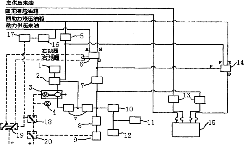
[0016] Embodiment 1: see figure 1 , the aircraft automatic refueling emergency hydraulic system, including hydraulic system and electrical system, in the hydraulic system, one end of the air release valve 1 is connected with the air release port of the emergency fuel tank 2, and the oil outlet of the emergency fuel tank 2 is connected with the emergency electric pump 3, and the emergency fuel tank The oil return port of 2 is connected to the oil return circuit of the emergency system, the oil suction port of the emergency electric pump 3 is connected to the emergency oil tank 2, the oil outlet of the emergency electric pump 3 is connected to the one-way valve 7, and the pipeline of the power-assisted hydraulic oil tank is connected to the emergency oil tank 2 The constant pressure one-way valve 5 is installed in the circuit between them, the A port of the double-position electromagnetic switch 6 is connected with the pressure supply oil circuit of the booster hydraulic system, ...

Embodiment 2

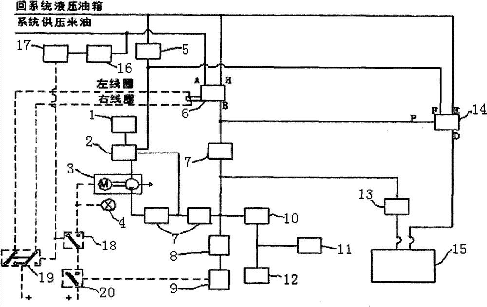
[0030] Example 2: see figure 2 , the system of this embodiment also includes a hydraulic system and an electrical system. The difference between the cross-linking of the hydraulic system and that of Embodiment 1 is that the pressure supply form of the hydraulic system in the non-failure failure mode is a single hydraulic system, and the hydraulic system and the emergency hydraulic system The hydraulic coupling part has only one hydraulic oil filter, and the horizontal tail booster 15 is a single cavity, while the horizontal tail booster in Embodiment 1 is a double-cavity horizontal tail booster; the cross-linking form of the components of the electrical system corresponds to that of Embodiment 1 same.

[0031] The hydraulic system of this embodiment also uses the emergency pressure accumulator 10 to refuel and maintain the pressure of the emergency hydraulic system, and controls the switching between the oil circuits of the two systems through the switching valve 14 . When t...


PUM


Abstract

The invention relates to an automatic oiling type emergency hydraulic system of an airplane, comprising a hydraulic system and an electrical system. An oil path is switched through a switching valve; an emergency accumulator in an oil path of an assisted hydraulic system fills oil and supplies the pressure to the emergency accumulator; horizontal stabilizers are continuously operated to enable the pressure of the emergency hydraulic system to change; and an emergency electric pump is started to supply the pressure to the emergency system and fill oil and supplied pressure to the emergency accumulator. Hydraulic oil of the emergency hydraulic system comes from the assisted hydraulic system without being added from the outside and the whole process can be automatically finished; and the emergency hydraulic system maintains the pressure and automatically discharges the hydraulic oil which returns to an assisted oil tank. The emergency hydraulic system is fully coupled with the assisted hydraulic system so as to greatly reduce the workload for maintenance. When a main hydraulic system and the assisted hydraulic system have faults and fail, the operation safety of the horizontal stabilizers can be ensured and the airplane can safely land by the emergency hydraulic system.

Description

technical field [0001] The invention relates to an aviation hydraulic system, in particular to an aircraft automatic refueling emergency hydraulic system. Background technique [0002] The design of the aircraft hydraulic system is developing in the direction of high pressure and electro-hydraulic combination, and the aircraft control requires the hydraulic system to meet at least one fault operation and secondary fault safety. The emergency hydraulic system is to ensure the operation of the key parts of the product in the event of failure of the main and auxiliary pressure supply systems (secondary failure), and it must be independent of other systems. Therefore, in addition to the main and auxiliary hydraulic systems, the aircraft is also equipped with an emergency hydraulic system to provide an emergency hydraulic source for one chamber of the double-chamber actuator of the horizontal tail, forming a hydraulic system with three redundant degrees, which improves the safety...

Claims


Application Information

Patent Timeline
Patent Type & Authority Patents(China)
IPC IPC(8): B64D37/00F15B1/02
Inventor 刘殿印张立圣王莉印正锋哈晓春焦奇峰姜曼琳黎国荣高洁毛德爱邵明华
Owner JIANGXI HONGDU AVIATION IND GRP
Why Eureka
Try Eureka