Electromagnetic clutch

A technology of electromagnetic clutch and electromagnetic coil, applied in clutches, magnetic drive clutches, non-mechanical drive clutches, etc., can solve problems such as increased device cost

Inactive Publication Date: 2010-10-27
DAIKEN CO LTD
View PDF5 Cites 8 Cited by
  • Summary
  • Abstract
  • Description
  • Claims
  • Application Information

AI Technical Summary

Problems solved by technology

[0002] Conventionally, in the case where a plurality of driven parts are separately driven, if the number of driving devices, such as motors, etc. equal to the number of driven parts is provided, the cost of the device increases

Method used


Image

  • Electromagnetic clutch
  • Electromagnetic clutch
  • Electromagnetic clutch

Examples


Embodiment Construction

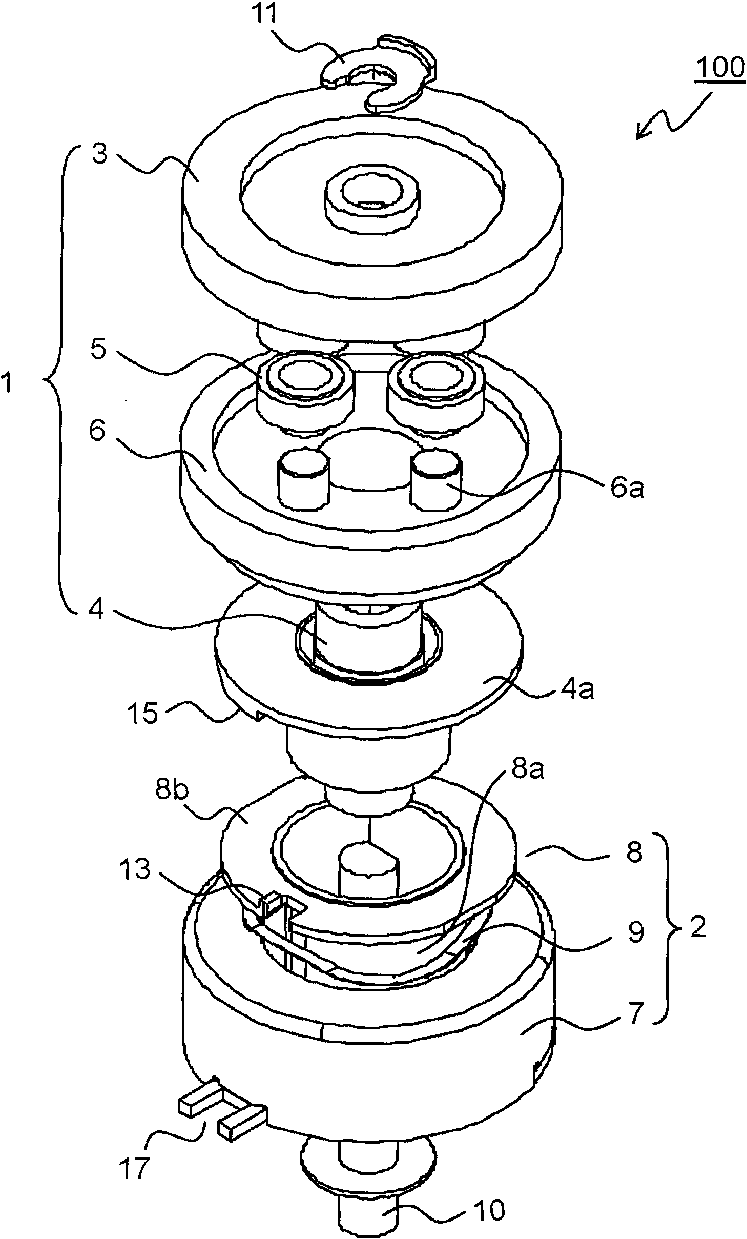
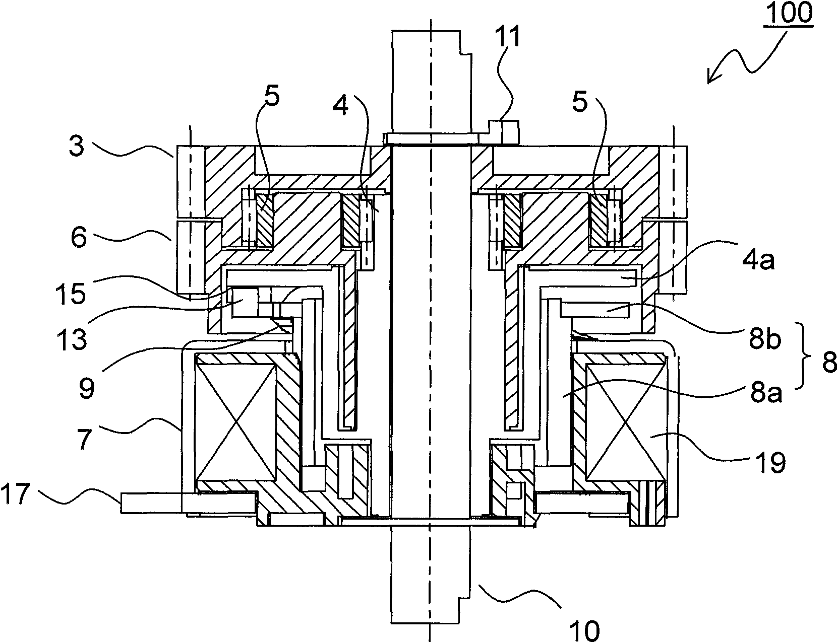
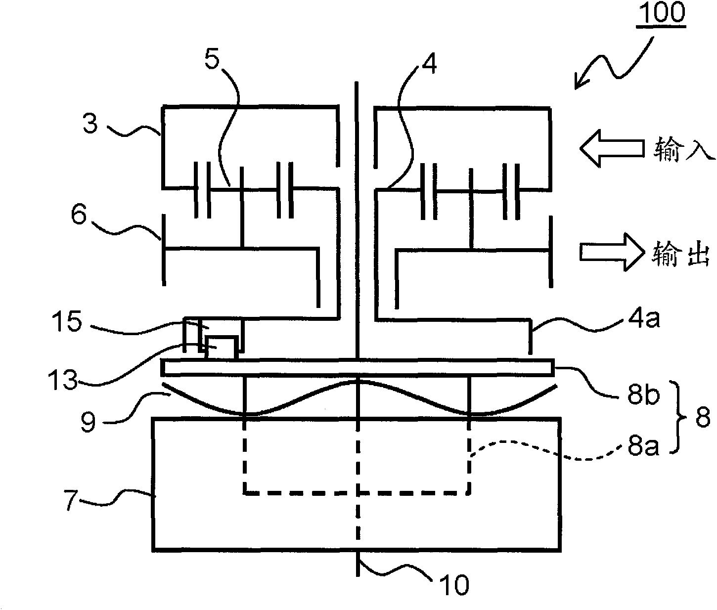
[0026] Hereinafter, embodiments of the present invention are described with reference to the accompanying drawings, figure 1 is an exploded perspective view of the planetary gear clutch according to the first embodiment of the present invention. Such as figure 1 As shown in , a planetary gear clutch (hereinafter, simply referred to as a clutch) 100 is an electromagnetic clutch including a planetary gear mechanism 1 and an electromagnetic solenoid 2 . The planetary gear mechanism 1 includes: an internal gear 3 including gear teeth formed on the inner surface side thereof; a sun gear 4 provided on the same shaft at the central portion inside the internal gear 3; one or more (here are 4) planetary gears 5, which are provided between the outer peripheral surface of the sun gear 4 and the inner surface of the internal gear 3; 6a.

[0027] The electromagnetic solenoid 2 includes an electromagnetic coil portion 7 that forms a magnetic circuit when an inner coil 19 is energized (se...


PUM


Abstract

A clutch 100 includes: an internal gear 3 that includes a gear tooth formed on an inner-surface side thereof; a sun gear 4 that is disposed on the same shaft at a central portion of the inner side of the internal gear 3; one or more planetary gears 5 that are disposed between an outer circumferential surface of the sun gear 4 and an inner surface of the internal gear 3; a carrier 6 that is provided with a boss portion 6a that supports rotatably the planetary gear 5; an electromagnetic coil portion 7; a rotation limit member 8 that is slidably inserted into the electromagnetic coil portion 7 in a shaft direction and selectively disposed at a first position for limiting rotation of the internal gear 3 or the sun gear 4 or at a second position for permitting the rotations of the internal gear 3 and the sun gear 4; and an elastic member 9 that is disposed between the electromagnetic coil portion 7 and the first flange portion 8b of the rotation limit member 8.

Description

technical field [0001] The present invention relates to a planetary gear type clutch using a planetary gear mechanism. Background technique [0002] Conventionally, in the case where a plurality of driven parts are driven separately, if driving devices such as motors etc. are provided in number equal to the number of driven parts, the cost of the device increases. In order to avoid this, generally the driven part is driven by using one driving device; and a clutch mechanism that performs transmission and interruption of the driving force is provided between the driving device and the driven part. [0003] As a clutch mechanism, JP-A-2006-292120 discloses a planetary gear type clutch including a planetary gear mechanism consisting of: a rotatable internal gear; a sun gear, which is rotatably disposed inside a central portion of the gear; a planetary gear that meshes with the sun gear and the inner side of the internal gear and rotates around the sun gear while rotating aroun...

Claims


Application Information

Patent Timeline
Patent Type & Authority Applications(China)
IPC IPC(8): F16D27/02
CPCF16D27/118
Inventor 楠田敏明
Owner DAIKEN CO LTD
Why Eureka
Try Eureka