
Hundred picosecond pulse width measuring instrument

A width measurement, picosecond pulse technology, applied in the field of 100 picosecond pulse width measuring instrument, can solve the problem of no measuring instrument

Inactive Publication Date: 2010-10-27
SHANGHAI INST OF OPTICS & FINE MECHANICS CHINESE ACAD OF SCI
View PDF5 Cites 3 Cited by
  • Summary
  • Abstract
  • Description
  • Claims
  • Application Information

AI Technical Summary

Problems solved by technology

However, there is no suitable measuring instrument for the laser pulse width in the infrared band in this range.

Method used


Image

  • Hundred picosecond pulse width measuring instrument
  • Hundred picosecond pulse width measuring instrument
  • Hundred picosecond pulse width measuring instrument

Examples


Embodiment Construction

[0017] The present invention will be further described below in conjunction with the embodiments and accompanying drawings, but the protection scope of the present invention should not be limited thereby.

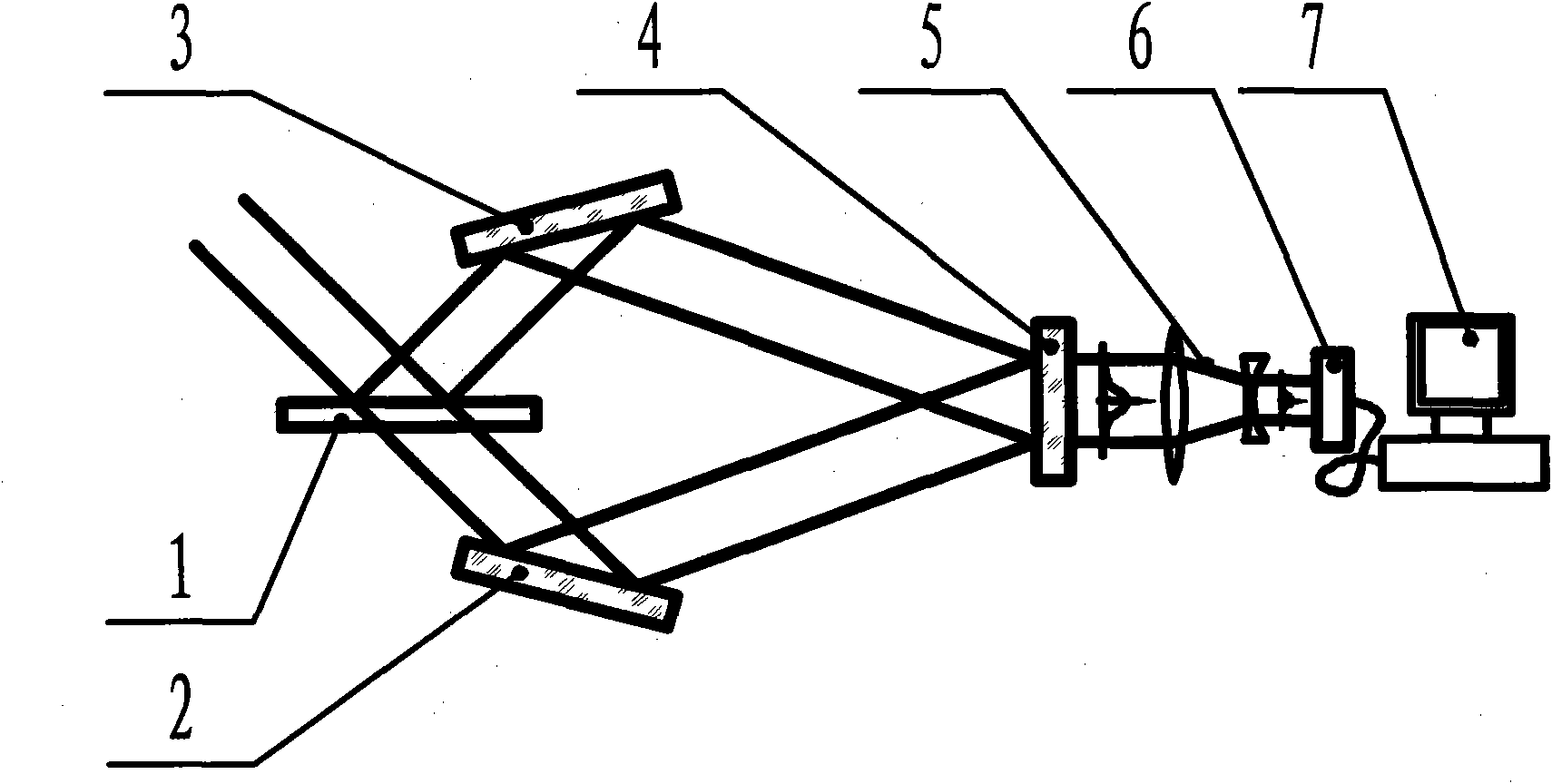
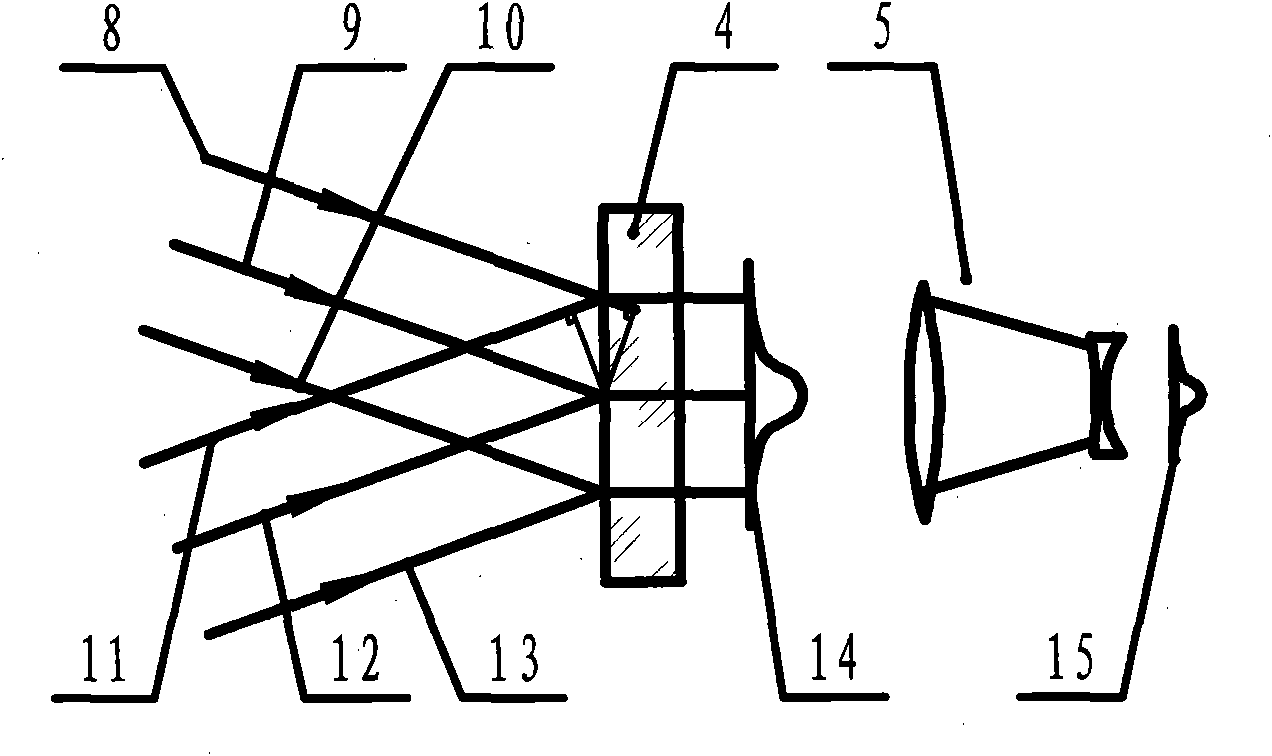
[0018] see first figure 1 , figure 1 It is a schematic diagram of the structure of the picosecond pulse width measuring instrument of the present invention. It can be seen from the figure that the picosecond pulse width measuring instrument of the present invention comprises a beam splitter 1, a first light guiding mirror 2, and a second light guiding mirror 3. Non-linear frequency doubling crystal 4, optical imaging system 5, CCD detector 6 and data acquisition and processing system 7, the positional relationship of each component is as follows:

[0019] The incident picosecond laser pulse to be measured passes through the beam splitter 1 to divide the pulse to be measured into transmitted light and reflected light. The transmitted light passes through the first light gui...


PUM


Abstract

The invention relates to a hundred picosecond pulse width measuring instrument which comprises a spectroscope, a first light guide reflector, a second light guide reflector, a non-linear frequency doubling crystal, an optical imaging system, a CCD (Charge Coupled Device) detector and a data acquisition and processing system, wherein the position relation of all components is shown as follow: an incident picosecond laser pulse to be measured divides a pulse to be measured into transmitted light and reflected light through the spectroscope; the transmitted light and the reflected light respectively pass through the first light guide reflector and the second light guide reflector and simultaneously enter into the non-linear frequency doubling crystal to generate a frequency doubling signal; and the frequency doubling signal is imaged on the CCD detector through the optical imaging system, and the data acquisition and processing system is used for finishing acquisition and data processing. The measuring instrument has the maximum measurable pulse time range of 150ps and the resolution ratio of 0.2ps.

Description

technical field [0001] The invention relates to laser parameter measurement, in particular to a hundred picosecond pulse width measuring instrument. Background technique [0002] At present, the only measuring instrument capable of measuring ultrashort pulses of about 100 picoseconds is the streak camera, while the infrared streak camera is an international embargo item and cannot be purchased in China. [0003] In the field of ultrashort pulse time measurement, pulses greater than 150 ps can be measured by fast-response photocells and high-bandwidth digital oscilloscopes, and pulses less than 20 ps can be measured by commercial single-shot pulse autocorrelators. The laser pulse width in the visible light band from 20 ps to 150 ps can be measured with a visible light streak camera. However, there is no suitable measuring instrument for the laser pulse width in the infrared band in this range in scientific research. [0004] In 1995, R.A.Ganeev proposed the scheme of autoco...

Claims


Application Information

Patent Timeline
IPC IPC(8): G01J11/00
Inventor 欧阳小平朱宝强黄奎喜杨琳刘崇朱健强
Owner SHANGHAI INST OF OPTICS & FINE MECHANICS CHINESE ACAD OF SCI
Learn More