
Slide-way structure

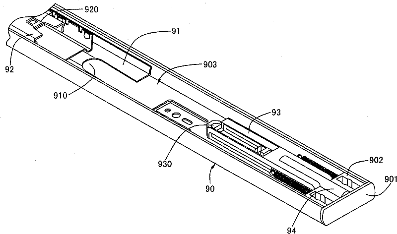
A slide rail and inner slide rail technology, which is applied to furniture parts, home appliances, drawers, etc., can solve the problems of limited length of the inner slide rail 92, limited length of the full extension, and impracticality, so as to reduce the manufacturing cost and increase the full extension. Proportion, simplifying the troublesome effect

Active Publication Date: 2012-07-11
苏州南俊商贸有限公司
View PDF0 Cites 0 Cited by
  • Summary
  • Abstract
  • Description
  • Claims
  • Application Information

AI Technical Summary

Problems solved by technology

And because the buffer 94 itself and the push rod have a considerable length, they occupy part of the length of the outer slide rail 90, and when the inner slide rail 92 resets automatically, it needs to indirectly push against the buffer 94 to have a buffering effect, so the inner slide The length of the rail 92 is quite limited, so the overall length of the body will also be quite limited, so that this existing design is not practical
[0007] Furthermore, the overall design of the slide rail, in addition to the above-mentioned full extension length, the size adaptability of the reset unit and the outer slide rail is another key point. Generally, the reset unit uses the inner wall of the outer slide rail as the track, so the reset unit must be in line with the outer slide rail. The inner diameter and width of the slide rails must match, otherwise it will not be able to move along the outer slide rails, but in this case, when corresponding to different sizes of outer slide rails, it is necessary to design reset units of different sizes to adapt to the outer slide rails. has its inconvenience
The applicant of the present invention, in view of the above-mentioned two important points of the overall full length of the slide rail and the adaptability of the size, often cannot be taken into account, so the applicant of the present invention developed and improved this case, hoping to improve the deficiencies in the prior art with the structure of this case

Method used


Image

  • Slide-way structure
  • Slide-way structure
  • Slide-way structure

Examples


Embodiment Construction

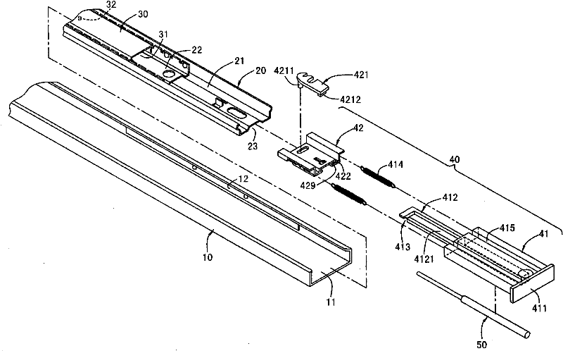
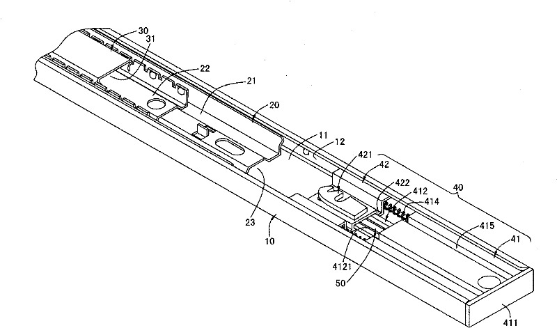
[0056] see figure 2 and image 3 As shown, it is a schematic diagram of decomposition and assembly of the first embodiment disclosed in the present invention. The slide rail structure disclosed in the first embodiment of the present invention includes an outer slide rail 10 , a middle slide rail 20 , an inner slide rail 30 , a reset unit 40 and a buffer member 50 . Some of the structural components and actuation methods belong to the prior art, and are not the subject of protection in this case, so the actuation principles of these components will not be described in detail, but it is not limited to this, and it is described in advance here.

[0057] The outer slide rail 10 is roughly a concave elongated structure, which has an outer rail space 11 inside, and a ball group 12 is arranged in the outer rail space 11, and the outer rail space 11 can be used for the middle slide rail 20 and the inner slide rail. 30 is assembled with the reset unit 40 , and the middle slide rail ...


PUM


Abstract

The utility model discloses a slide-way structure, the body of which mainly comprises an outer slide-way, a middle slide-way, an inner slide-way, a restoration unit and a buffering unit. A jook space is arranged at the bottom of the middle slide-way. The inner slide-way slips in the space of the middle slide-way. The restoration unit is mounted at one end of the outer slide-way, the restoration unit comprises a fixed body which is fixed in the space of the outer slide-way, a sliding track arranged in the space of the outer slide-way, a movable body which can slide along the sliding track, at least one elastic element arranged between the fixed body and movable body, a locking piece pivoted on the movable body, and a guiding piece which is arranged on the inner slide-way and can form temporary lock joint with the locking piece. When the middle slide-way slips in the space of the outer slide-way, a locking mechanism or a connecting mechanism is arranged in the sliding track for temporarily fixing the movable body, while the sliding track is pivoted in a jook space, thus the middle slide-way cannot be blocked by the sliding track when slipping in the space of the outer slide-way. By the method, the body is provided with better fully expanded length.

Description

technical field [0001] The present invention relates to a sliding rail structure, in particular to a sliding rail structure with a relatively large reset stroke. Background technique [0002] At present, the common drawers, keyboard drawers, etc., for the convenience of pulling out and resetting, will combine the slide rail device with inner, middle and outer slide rails. The slide rail device is fixed on the bottom of the book frame or table by using the outer slide rail. The inner slide rail is combined with the outer side of the drawer and keyboard drawer, so that the drawer, keyboard drawer, etc. can be based on the outer slide rail fixed to the book frame and desktop, and through the gap between the inner and outer slide rails. The steel ball achieves the labor-saving pull-out and push-in reset functions of drawers and keyboards. [0003] In order to make the middle and inner slide rails provide a positioning and automatic reset effect when they are stored inside the o...

Claims


Application Information

Patent Timeline
Patent Type & Authority Patents(China)
IPC IPC(8): A47B88/16A47B88/493
CPCA47B88/047A47B88/467
Inventor 杨瑞链
Owner 苏州南俊商贸有限公司
Learn More