Eureka AIR delivers breakthrough ideas for toughest innovation challenges, trusted by R&D personnel around the world.

Device for receiving a RF signal with loop-through output and method for looping a RF input signal through a device for receiving RF signals

一种输入信号、信号的技术,应用在传输系统、图像通信、彩色电视的零部件等方向,能够解决失真补偿等问题

Inactive Publication Date: 2010-10-27
NXP BV
View PDF2 Cites 1 Cited by
  • Summary
  • Abstract
  • Description
  • Claims
  • Application Information

AI Technical Summary

Problems solved by technology

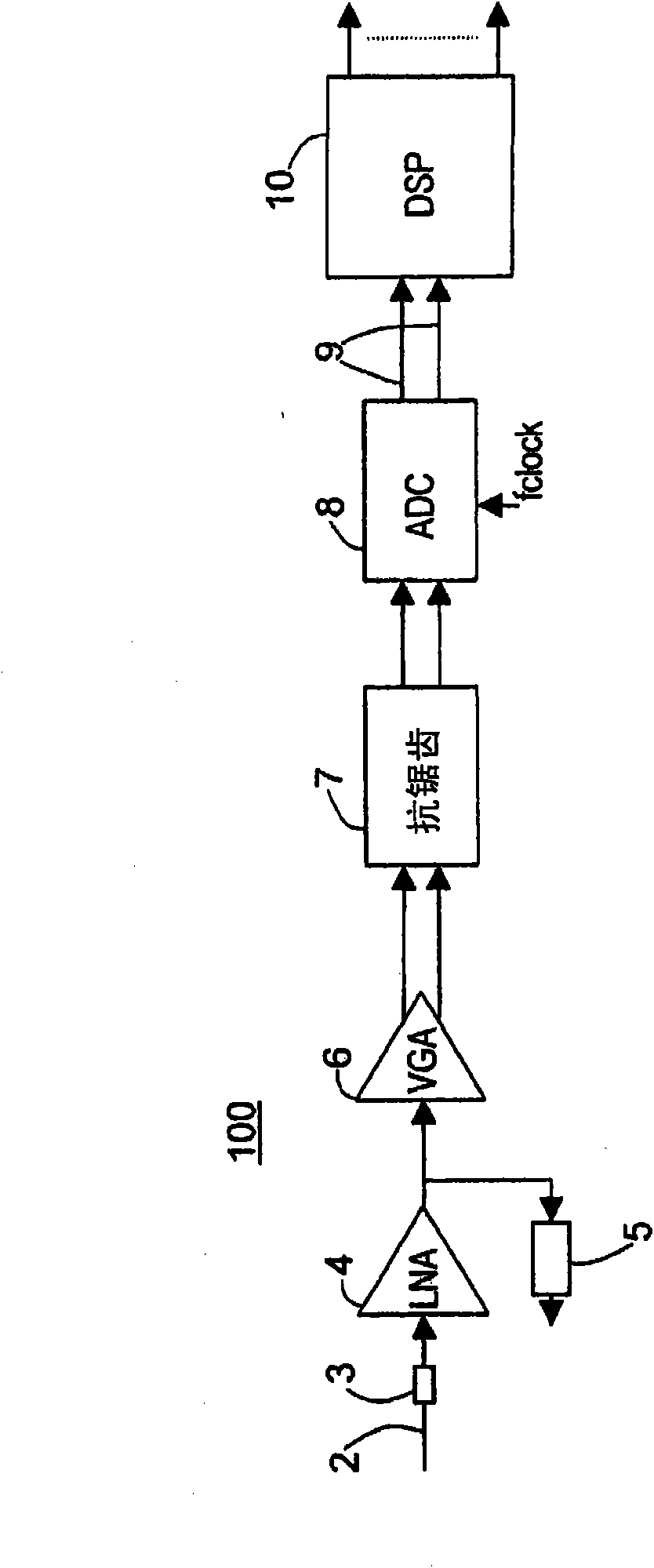
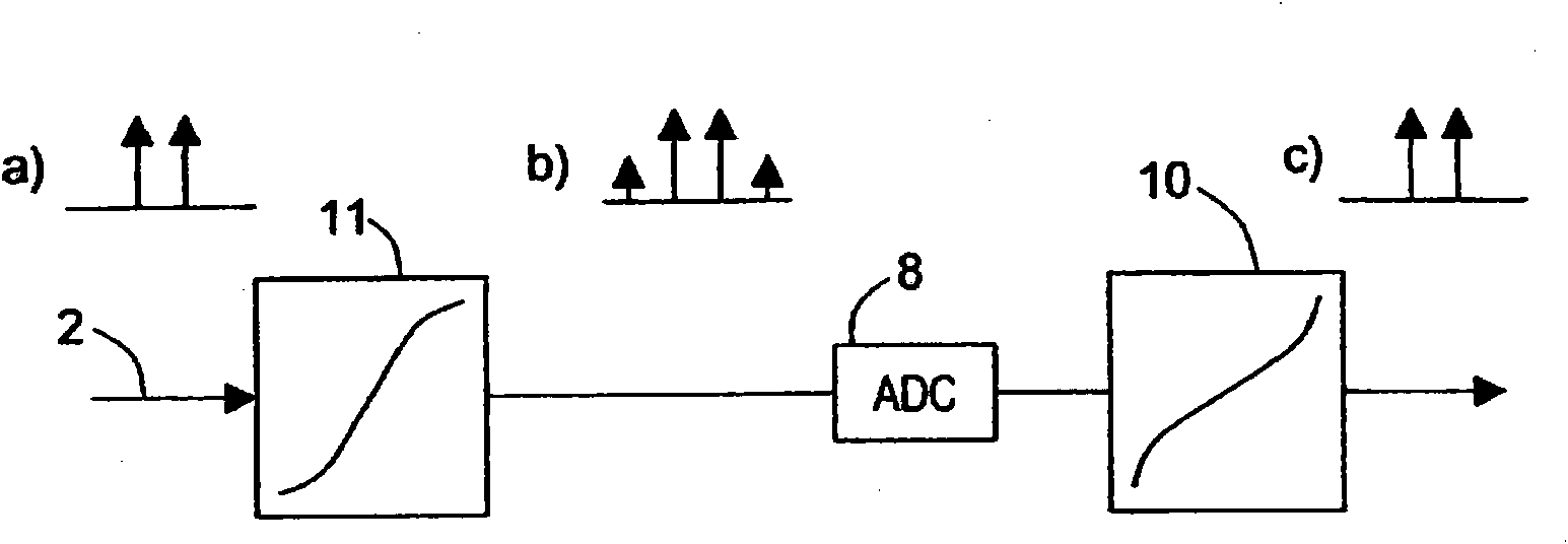
[0008] However, if the analog pre-processing circuit 11 including the low-noise amplifier 4 as a buffer is simplified using digital signal processing in the digital signal processor 10, a problem arises that the distortion generated in the buffer does not appear in the Loop output 5 provides the loop RF signal that is compensated for

Method used


Image

  • Device for receiving a RF signal with loop-through output and method for looping a RF input signal through a device for receiving RF signals
  • Device for receiving a RF signal with loop-through output and method for looping a RF input signal through a device for receiving RF signals
  • Device for receiving a RF signal with loop-through output and method for looping a RF input signal through a device for receiving RF signals

Examples


no. 1 example

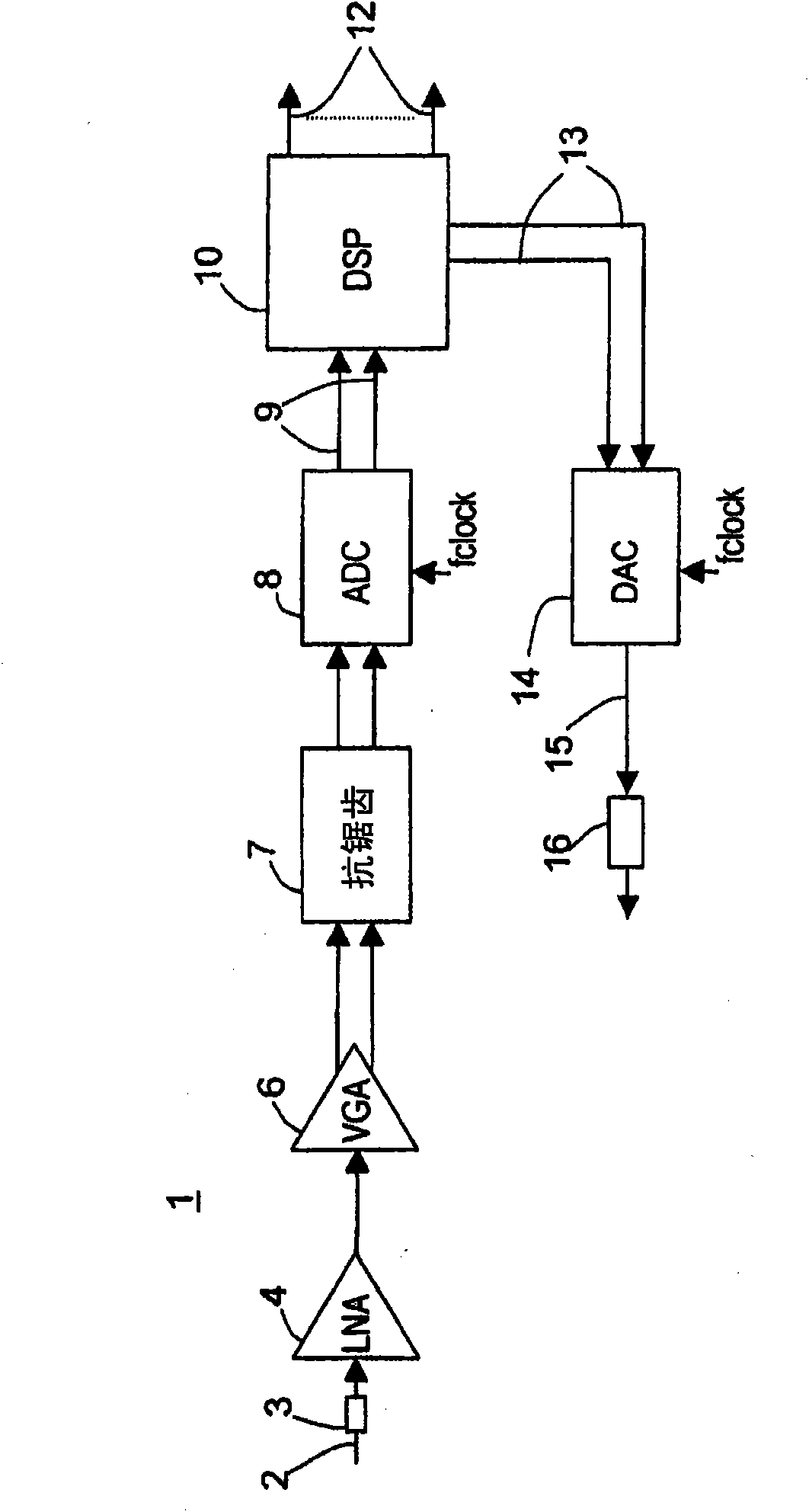
[0028] exist image 3 A device for receiving an RF signal with a loop output according to a first embodiment is illustrated in . exist image 3 In an embodiment, the means for receiving the RF signal is an RF receiver, which can be used, for example, in a DVD recorder or the like. refer to figure 1 Components described will be denoted by the same reference numerals as thereto.

[0029] exist image 3 The apparatus for receiving an RF signal 1 shown in is implemented as a direct sampling multi-channel RF tuner. as in image 3As shown in , an RF input signal 2 is provided to input 3. For example, RF input signal 2 is an analog antenna signal received from a TV antenna. The RF input signal 2 is buffered with a low noise amplifier (LNA) 4 . Furthermore, after the LNA 4 , the RF input signal 2 is passed to a variable gain adjustment circuit (VGA) 6 , an anti-aliasing circuit 7 , and an analog-to-digital converter (ADC) that converts the RF input signal 2 into a digital sign...

no. 2 example

[0033] Figure 4 A second embodiment of the invention is illustrated in . exist Figure 4 The device 21 for receiving RF signals shown in corresponds to the image 3 The device described, therefore only the differences are described below. exist Figure 4 shown in the device 21 with image 3 The arrangement 1 shown in is different in that an additional buffer 17 is provided between the digital-to-analog converter 14 and the loop output 16 . In this case the digital signal processor 10 is provided so that the non-linear distortion introduced by the buffer 17 is compensated by suitable predistortion. This provides a high quality loop signal even though additional buffering that introduces non-linear distortion occurs in the loop from the input to the loop output 16 .


PUM


Abstract

A device for receiving a RF signal (1; 21) with loop-through output (16) is provided. The device comprises: an input (3) receiving a RF input signal (2); an analog- digital converter (8) converting the RF input signal (2) to a digital signal (9); a digital signal processing unit (10) digitally processing the digital signal (9); a digital-analog converter (14) converting the processed digital signal (13) to a loop-through RF signal (15) corresponding to the RF input signal (2); and a loop-through output (16) outputting the loop-through RF signal (15).

Description

technical field [0001] The present invention relates to a device for receiving an RF signal with a looped output and a method for looping an RF input signal by receiving the RF signal. More particularly, the present invention relates to an apparatus for receiving an RF signal having a loop output, wherein the RF input signal is digitized before being output as a loop RF signal at the loop output. Background technique [0002] In the context of this application, an RF signal is to be understood as an analog signal comprising a plurality of frequencies, for example, frequencies in the band 45 to 1040 MHz. A large number of different devices for receiving RF (Radio Frequency Signals) signals can be found on the market. Examples of such devices are TV tuners for cable modems, DVD recorders, set top boxes, USB dongles, PC add-on cards, TVs and other RF equipment. In these devices, an RF input signal is applied to the input of the device and the device is adapted to sample the R...

Claims


Application Information

Patent Timeline
Patent Type & Authority Applications(China)
IPC IPC(8): H04B1/12H04B1/18H04N5/775
CPCH04B1/12H04B1/18
Inventor 约翰尼斯·H·A·布雷克曼康斯坦丁诺斯·多丽丝埃尔温·扬森
Owner NXP BV
Why Eureka
Eureka Blog
Learn More