Closure mechanism of a hollow fiber module and hollow fiber module

A hollow fiber technology, applied in chemical instruments and methods, semi-permeable membrane separation, membrane technology, etc., can solve the problems of reduced separation performance of hollow fiber membranes, partial drying of hollow fiber membranes, and reduced airtightness, so as to maintain separation performance , Improve the effect of sterility and high airtightness

Active Publication Date: 2010-11-03
ASAHI KASEI MEDICAL CO LTD
View PDF7 Cites 1 Cited by
  • Summary
  • Abstract
  • Description
  • Claims
  • Application Information

AI Technical Summary

Problems solved by technology

In the case of using the above-mentioned closing method, loads are applied to the plate 103 and the fixing member 104 due to temperature and pressure, for example, deformation and deterioration of the plate 103 and the fixing member 104 may occur, and the airtightness of the liquid flow nozzle 101 after the sterilization treatment may decrease.
[0008] If the airtightness of the liquid flow nozzle is lowered after the sterilization treatment, for example, from the time of shipment of the hollow fiber module to the actual use, there is a possibility that bacteria may enter the casing.
In addition, the water in the casing volatilizes and is discharged outside the casing, for example, the water in the casing decreases to partially dry the hollow fiber membrane, and the separation performance of the hollow fiber membrane at the beginning of use may decrease.

Method used


Image

  • Closure mechanism of a hollow fiber module and hollow fiber module
  • Closure mechanism of a hollow fiber module and hollow fiber module
  • Closure mechanism of a hollow fiber module and hollow fiber module

Examples


Embodiment Construction

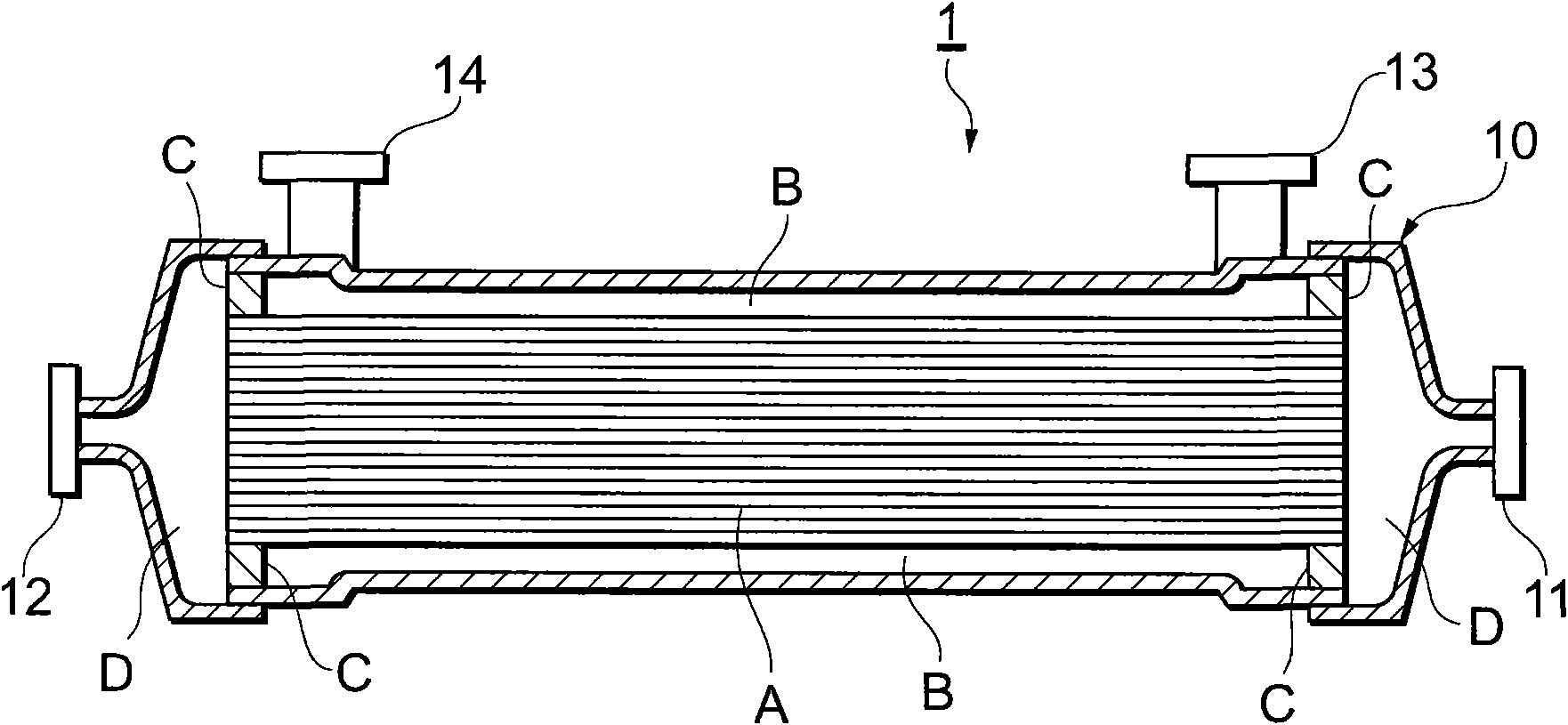
[0033] Hereinafter, preferred embodiments of the present invention will be described with reference to the drawings. figure 1 It is a cross-sectional view schematically showing the configuration of the hollow fiber module 1 to which the sealing mechanism of the present embodiment is applied.

[0034] For example, if figure 1 As shown, the hollow fiber module 1 includes: a hollow fiber membrane bundle A is accommodated along the length direction, and a cylindrical casing 10 with both ends closed; Two primary liquid-passing nozzles 11 and 12 connected internally; two secondary liquid-passing nozzles 13 and 14 formed on the outer peripheral side of the casing 10 and communicating with the outer peripheral space B of the hollow fiber membrane bundle A in the casing 10 .

[0035]Both ends of the hollow fiber membrane bundle A are fixed to the inner wall surface of the casing 10 by the sealing agent C. With the encapsulant C, the housing 10 is formed with an outer peripheral spa...


PUM


Abstract

The invention provides a closure mechanism of a hollow fiber module and the hollow fiber module, capable of keeping high tightness of the hollow fiber module even though the bactericidal treatment is performed. The closure mechanism of the hollow fiber module comprises: an obstruction component capable of being embedded into a primary liquid-flowing nozzle and closing the primary liquid-flowing nozzle; a closure component mounted on a secondary liquid-flowing nozzle and capable of closing the secondary liquid-flowing nozzle; an inner-side obstruction component capable of being embedded into the secondary liquid-flowing nozzle at the inner side of the closure component and obturating the secondary liquid-flowing nozzle, wherein the closure component freely deforms and the inner-side obstruction component is pressed into the secondary liquid-flowing nozzle when the closure component is mounted on the secondary liquid-flowing nozzle. The inner-side obstruction component comprises an access and the inner space is communicated with the cirumferential space by the access when the inner-side obstruction component is relatively lightly embedded into the secondary liquid-flowing nozzle at the inner side of the closure component. The inner-side space is not communicated with the cirumferential space by the access when the inner side of the inner-side obstruction component is relatively deeply embedded into the secondary liquid-flowing nozzle at the inner side of the closure component.

Description

technical field [0001] The present invention relates to a sealing mechanism of a hollow fiber module and a hollow fiber module. Background technique [0002] For example, in a virus remover that removes viruses from blood preparations, a blood purifier that removes unnecessary substances from blood during dialysis, etc., a specific substance capable of passing liquid such as blood preparations and separating them from the liquid has been used. Hollow fiber modules of hollow fiber membranes. [0003] The above-mentioned hollow fiber module includes, for example: a housing housing hollow fiber membrane bundles along the length direction; primary liquid nozzles formed at both ends of the length direction of the housing and communicating with the hollow fiber membrane bundles; formed in the housing The outer peripheral side of the hollow fiber membrane bundle is connected with the secondary liquid nozzle. Then, for example, a liquid is made to flow in from a primary liquid-pas...

Claims


Application Information

Patent Timeline
Patent Type & Authority Applications(China)
IPC IPC(8): B01D63/02
Inventor 糸濑隆生荒牧昌作
Owner ASAHI KASEI MEDICAL CO LTD
Why Eureka
Try Eureka