Oil separator

An oil separator and oil separation technology, applied in separation methods, filtration separation, membrane filters, etc., can solve problems such as distance deviation, thickness deviation of non-woven fabrics, and influence of oil separation performance, and achieve reduced pressure loss, high oil The effect of separation performance

Active Publication Date: 2020-03-31
NIFCO INC
View PDF8 Cites 0 Cited by
  • Summary
  • Abstract
  • Description
  • Claims
  • Application Information

AI Technical Summary

Problems solved by technology

[0004] However, in such an oil separator, the distance from the communication hole (introduction hole) to the surface of the nonwoven fabric becomes the main factor determining the flow rate of the gas blown onto the surface of the nonwoven fabric, etc., which greatly affects the oil separation performance.
However, since there is a large deviation in the thickness of the non-woven fabric, it is easy to have a large deviation in the distance from the communicating hole to the surface of the non-woven fabric.
Therefore, in conventional oil separators using non-woven fabrics, stable oil separation performance cannot be guaranteed

Method used


Image

  • Oil separator
  • Oil separator
  • Oil separator

Examples


Embodiment Construction

[0026] Embodiments of the present invention will be described below based on the drawings.

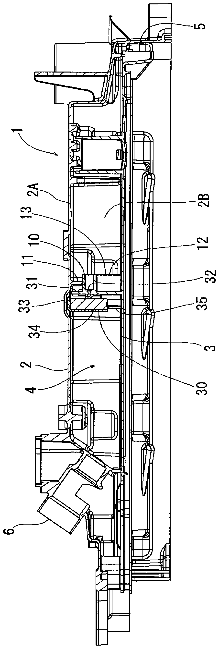
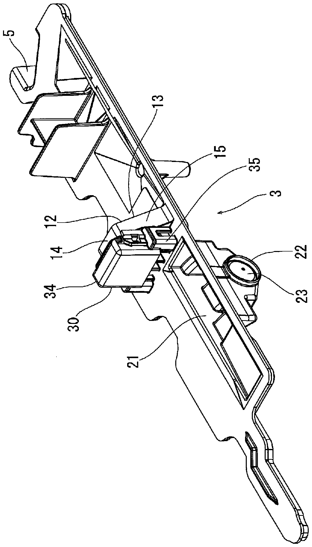
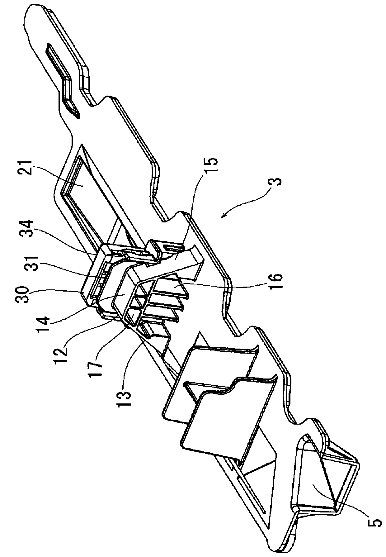
[0027] figure 1 The overall structure of the blow-by gas line 1 to which the oil separator 30 according to the embodiment of the present invention is installed is shown in . As shown in the figure, the blow-by gas line 1 is constituted by combining an upper member 2 and a lower member 3, and a fluid passage 4 is formed in a region surrounded by the two members. Blow-by gas (gas leaked from the combustion chamber of the engine) is introduced from the opening end 5 provided on the upstream side of the lower member 3 , and passes through the fluid passage 4 from the opening end 6 provided on the downstream side of the upper member 2 . discharge. In addition, the upper member 2 is a member integrated with the cylinder head cover of the engine, and has a top wall 2A and side walls 2B on both sides.

[0028] A partition wall 10 partitioning the fluid passage 4 into an upstream side and a ...


PUM


Abstract

Provided is an oil separator that precisely manages a gap between a gas introduction hole and a separation member and can secure stable and high separation performance. An oil separator 30 comprises:a wall part 31 that is provided with a plurality of orifices 32; and a holding part 34 that holds a separation member 33. A facing surface 33A of the separation member 33 is disposed along a front part 42A of a positioning part 42 having a plurality of openings 42D, and as a result, a spacing L between the orifices 32 and the facing surface 33A of the separation member 33 is precisely made to be adesired distance. Gas separated from oil smoothly flows downstream along a flow path formed by the openings 42D, and therefore pressure loss is reduced.

Description

technical field [0001] The present invention relates to an oil separator for separating oil from blowby gas. Background technique [0002] In vehicles such as automobiles, an oil separator is used to separate oil from blow-by gas. For example, Patent Document 1 (Japanese Patent No. 5152005) discloses a device that separates gas by spraying blow-by gas accelerated by throttling through communication holes to a nonwoven fabric arranged in a gas flow path. device containing oil mist. [0003] Patent Document 1: Japanese Patent No. 5152005 [0004] However, in such an oil separator, the distance from the communication hole (introduction hole) to the surface of the nonwoven fabric becomes the main factor determining the flow rate of the gas blown onto the surface of the nonwoven fabric, etc., which greatly affects the oil separation performance. . However, since there are large variations in the thickness of the nonwoven fabric, large variations tend to occur in the distance ...

Claims


Application Information

Patent Timeline
Patent Type & Authority Applications(China)
IPC IPC(8): F01M11/08F01M13/04
CPCB01D19/0031B01D2239/0618F01M13/0416F01M2013/0433B01D39/08F01M13/04
Inventor 中谷浩之高桥健二宇津桂亮
Owner NIFCO INC
Why Eureka
Try Eureka