Low-resistance slow-closure type check valve

A check valve, low resistance technology, applied in valve details, control valves, valve devices, etc., can solve problems such as large head loss, abnormal noise, damage to system pipelines and testing equipment, etc.

Inactive Publication Date: 2010-11-03
SHANGHAI PANDA MACHINEGRP CO LTD
View PDF3 Cites 4 Cited by
  • Summary
  • Abstract
  • Description
  • Claims
  • Application Information

AI Technical Summary

Problems solved by technology

[0002] The check valves used in the water supply and drainage system in the prior art generally have such a phenomenon due to structural reasons. When the check valve is in use, it seriously hinders the pressure of the water in the s

Method used


Image

  • Low-resistance slow-closure type check valve
  • Low-resistance slow-closure type check valve

Examples


Embodiment Construction

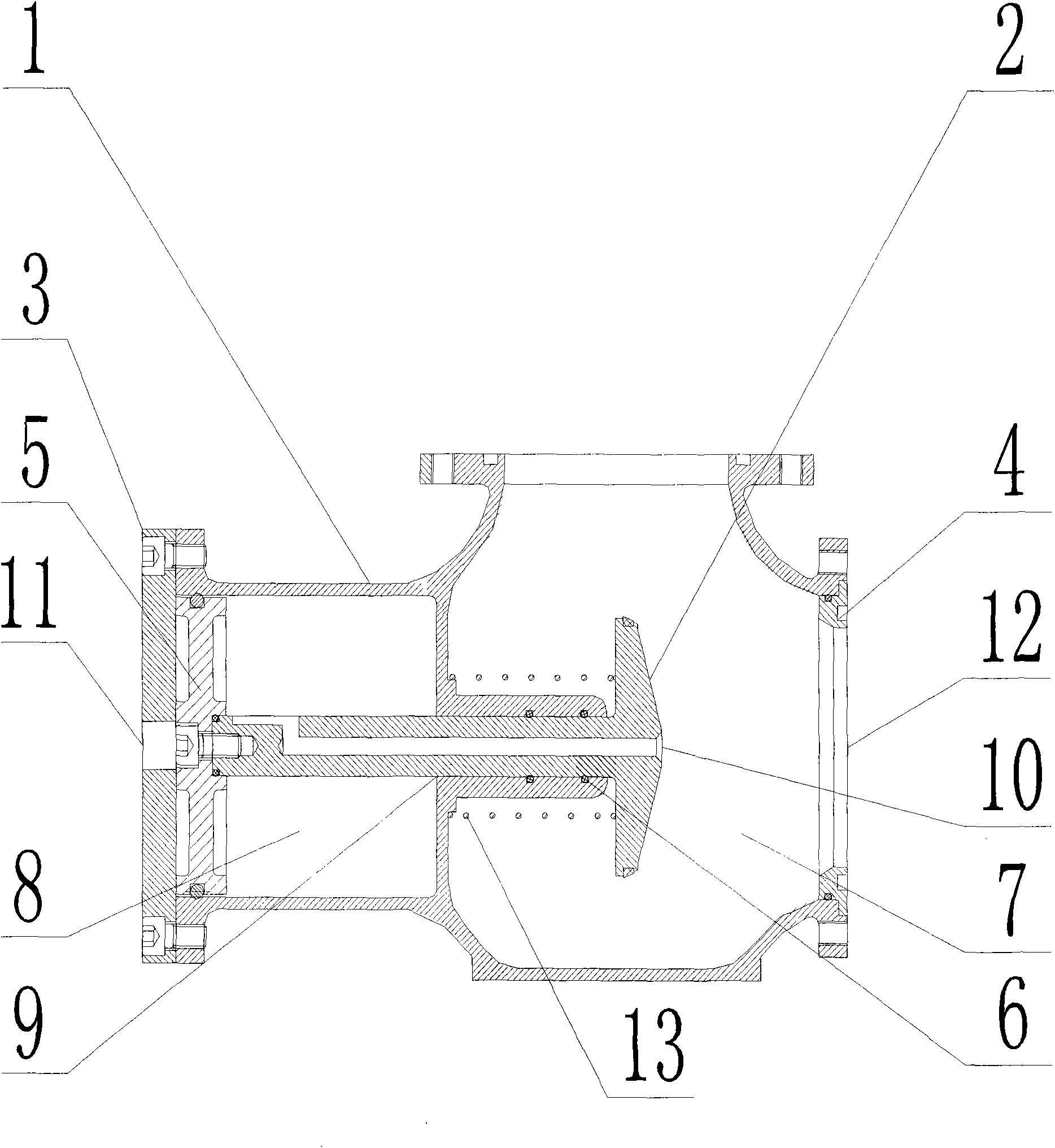
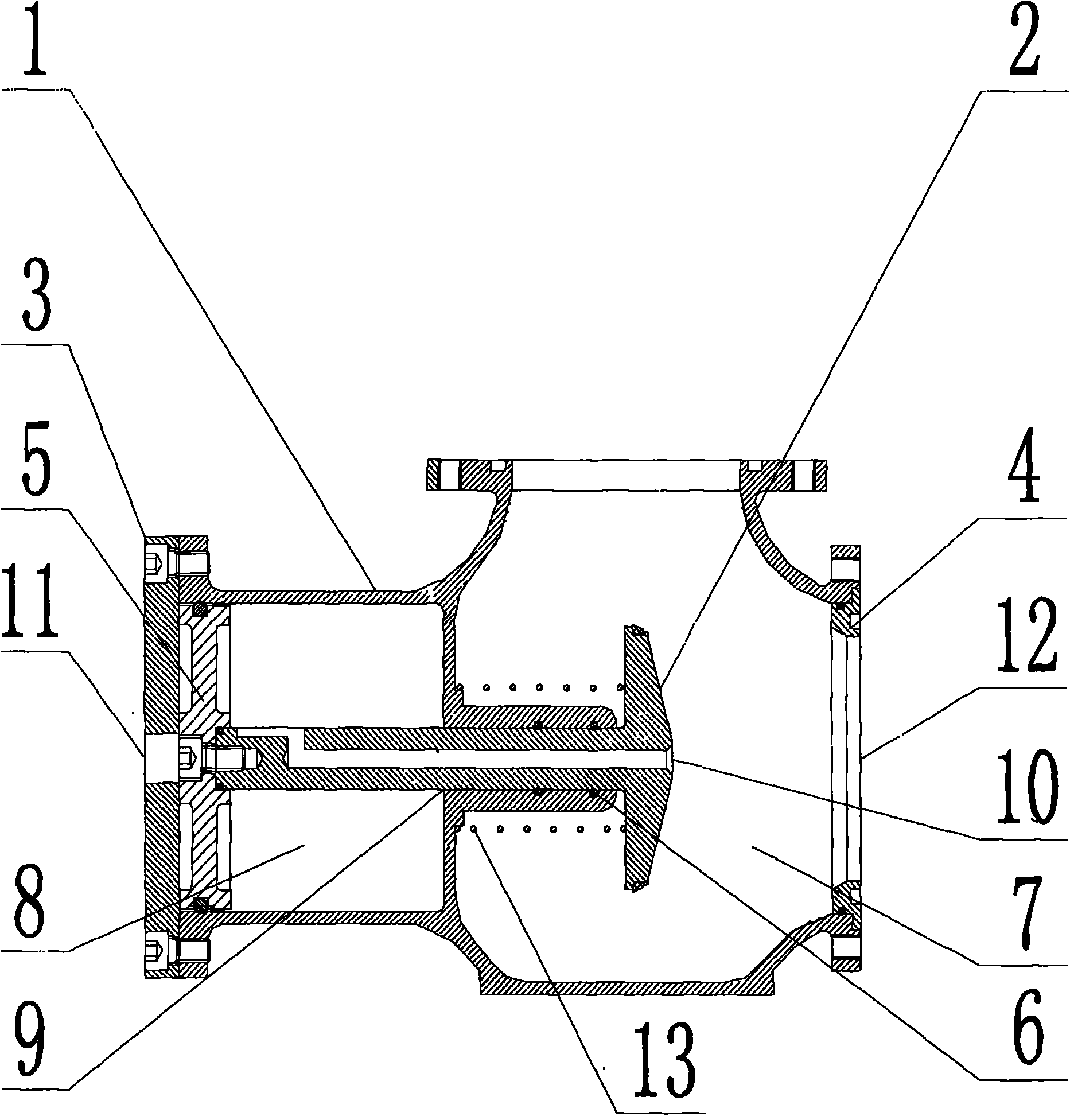
[0007] Low-resistance slow-closing check valve, including: valve body 1, valve disc 2, back cover 3, seal ring 4, piston 5, seal ring 6, valve body 1 is divided into flow chamber 7 and piston chamber 8, flow chamber 7 There is a connection hole 9 between the cavity 7 and the piston cavity 8, the shaft of the valve disc 2 can enter the piston cavity 8 through the hole 9, the shaft of the valve disc 2 enters the piston cavity 8 and connects with the piston 5, and the piston 5 The seal ring 6 is installed on the shaft of valve disc 2, and the seal ring 4 is installed at the water inlet 12, which solves the sealing problem. When the check valve is closed to supply water to the system, because there is a hole 10 on the disc 2, the high-pressure water will now enter the piston chamber 8 through the hole 10. There is an air circulation hole 11, so that the high-pressure water in the piston chamber 8 pushes the valve disc 2 to move forward, so that the water inlet 12 of the low-resist...


PUM


Abstract

The invention relates to a low-resistance slow-closure type check valve. Since a hollow hole is arranged in a valve clack, when flowing through the low-resistance slow-closure type check valve, high-pressure water firstly flows through a valve clack hole and then enters a piston cavity, and since a vent hole is arranged on a rear cover, a pressure difference is formed, the high-pressure water pushes a piston to operate backwards, the valve clack is driven to operate backwards, the valve is in an opening state, water operates in a barrier-less expedite environment, and hydraulic loss is correspondingly reduced greatly. When the pressure of the water inlet of the valve is reduced or water is stopped, the high-pressure water in the piston cavity and the system flows to the low-pressure part, a backflow state occurs, and because the valve clack and water are in a radial force operating state, the valve clack operates backwards slowly, the low-resistance slow-closure type check valve is finally in a closed state, the non-return purpose is achieved, and the water hammer is avoided.

Description

1: Technical field [0001] The invention relates to a check valve used in a water supply and drainage system, in particular to a slow-closing check valve with low resistance. Two: background technology [0002] The check valves used in the water supply and drainage system in the prior art generally have such a phenomenon due to structural reasons. When the check valve is in use, it seriously hinders the pressure of the water in the system, resulting in large head loss and high energy consumption. When the check valve performs the check function, severe water hammer and abnormal noise will occur, which will damage the pipeline and testing equipment in the system. Three: Invention content [0003] The object of the present invention is to design a check valve used in the water supply and drainage system, so that the hydraulic loss is small and the closure is delayed at the same time. [0004] The present invention adopts the following structure to achieve the above object. T...

Claims


Application Information

Patent Timeline
IPC IPC(8): F16K15/02F16K27/02
Inventor 池学聪周秀成谭红全
Owner SHANGHAI PANDA MACHINEGRP CO LTD
Why Eureka
Try Eureka