Digital potentiometer applied to direct-current working state

A digital potentiometer, DC working technology, applied in resistors, adjustable resistors, other resistor networks, etc., can solve the problems of many package pins, high cost, large package size, etc., to reduce package size, The effect of reducing product cost and reducing the number of package pins

Active Publication Date: 2012-04-25
FREMONT MICRO DEVICES SHENZHEN LTD
View PDF0 Cites 0 Cited by
  • Summary
  • Abstract
  • Description
  • Claims
  • Application Information

AI Technical Summary

Problems solved by technology

[0005] The purpose of the present invention is to provide a digital potentiometer applied to the DC working state, aiming to solve the problems that the digital potentiometer in the prior art occupies too many package pins, the package size is too large and the cost is too high

Method used


Image

  • Digital potentiometer applied to direct-current working state
  • Digital potentiometer applied to direct-current working state
  • Digital potentiometer applied to direct-current working state

Examples


Embodiment Construction

[0021] In order to make the object, technical solution and advantages of the present invention clearer, the present invention will be further described in detail below in conjunction with the accompanying drawings and embodiments. It should be understood that the specific embodiments described here are only used to explain the present invention, not to limit the present invention.

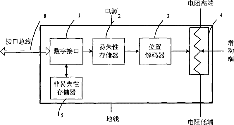
[0022] see figure 1 as shown, figure 1 It is a block diagram of a non-volatile digital potentiometer system in the prior art. The digital potentiometer system includes a non-volatile memory 5 , a digital interface 1 , a volatile memory 2 , a position decoder 3 and a variable resistor 4 . The non-volatile memory 5 is connected to the digital interface 1 , the digital interface 1 is connected to the volatile memory 2 , the volatile memory 2 is connected to the position decoder 3 , and the position decoder 3 is connected to the variable resistor 4 . From figure 1 It can be seen that the system nee...


PUM


Abstract

The invention relates to a digital potentiometer, and provides a digital potentiometer applied to a direct-current working state. The digital potentiometer comprises a digital logic unit, a variable resistor and a nonvolatile memory, wherein the digital logic unit further comprises a digital interface, a volatile memory and a position decoder; the digital interface is connected with the volatile memory; the volatile memory is connected with the position decoder; the position decoder is connected with the variable resistor; and the nonvolatile memory is connected with the digital interface andused for automatically storing the position of a sliding end of the variable resistor so as to simplify user operation. The two ends of the variable resistor are connected with direct-current voltages of which the voltage difference is more than a fixed numerical value, a high resistance end of the variable resistor is connected with a power wire of the digital logic unit, a low resistance end ofthe variable resistor is connected with a ground wire of the digital logic unit, and the high resistance end and the low resistance end are respectively used as the power wire and the ground wire of the digital logic unit, so that the number of packaging pins and the packaging size of the digital potentiometer can be reduced, the product cost is reduced and the system space is saved.

Description

technical field [0001] The invention relates to a digital potentiometer, in particular to a digital potentiometer applied to a DC working state. Background technique [0002] A digital potentiometer, unlike a mechanical potentiometer, has a wiper whose position is controlled by the value of an internal digital register. The N-bit potentiometer is to divide the total resistance RHL into 2n small resistors. When the value of the digital register is X, there are X small resistors connected between W and L. Therefore, changing the value of the register can change the position of the slider, and one-to-one correspondence. Digital potentiometers can be classified as non-volatile and volatile based on memory class. For volatile digital potentiometers, after the system is powered off, the position of the sliding end previously set will be lost; for non-volatile digital potentiometers, the position of the sliding end can be stored in the non-volatile memory, and the position of the...

Claims


Application Information

Patent Timeline
Patent Type & Authority Patents(China)
IPC IPC(8): H01C10/00H01C1/16
Inventor 邓锦辉刘桂云胡小波施爱群
Owner FREMONT MICRO DEVICES SHENZHEN LTD
Why Eureka
Try Eureka