
Control chip, primary side control circuit, power converter and control method thereof

A technology for power converters and control chips, which is applied in the direction of adjusting electrical variables, control/regulating systems, converting AC power input to AC power output, etc. and other problems to achieve the effect of reducing the number of package pins, realizing low cost and avoiding interference.

Pending Publication Date: 2021-02-23
SHENZHEN KIWI MICROELECTRONICS CO LTD
View PDF0 Cites 0 Cited by
  • Summary
  • Abstract
  • Description
  • Claims
  • Application Information

AI Technical Summary

Problems solved by technology

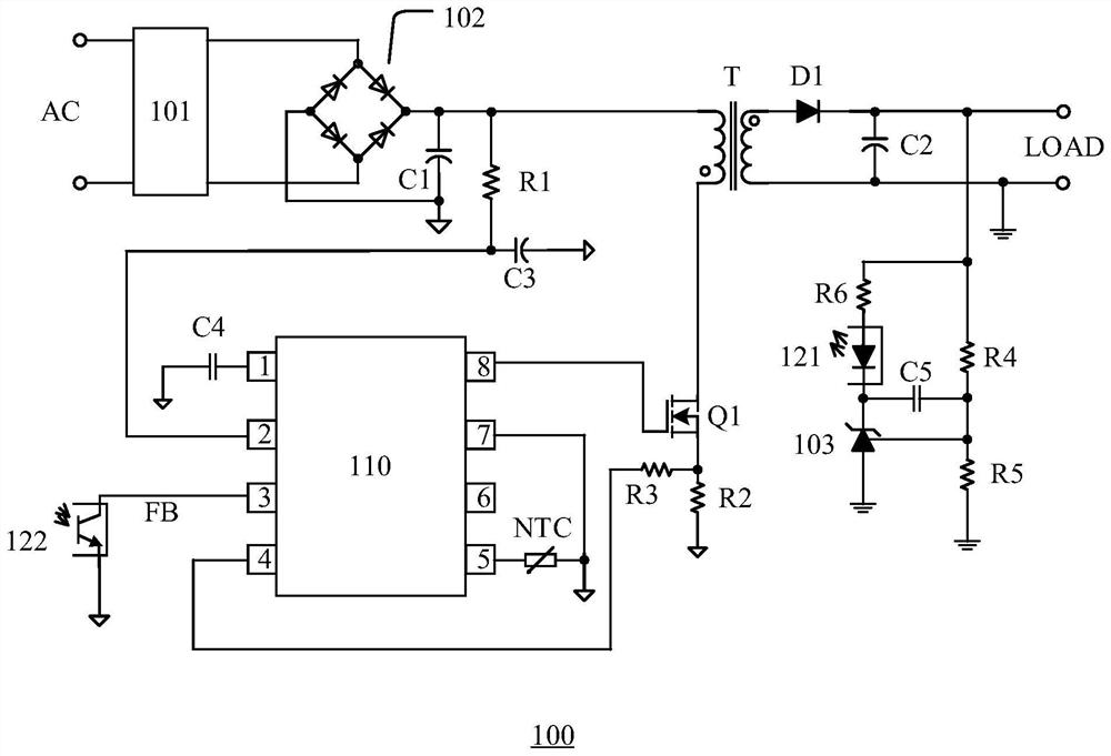
[0003] In the flyback power converter based on secondary side feedback, when the primary side control circuit involves more complex functions, it may need to include power input, grounding, output (output pulse width modulation signal to the control terminal of the switch tube), overload Functions such as protection, sampling (adjusting the pulse width modulation signal according to the sampling of the voltage of the primary side circuit), receiving feedback from the secondary side, setting protection parameters, etc. The method of multiplexing or realizing function multiplexing is more complicated, and the packaging cost is higher, which increases the implementation cost of the power converter

Method used


Image

  • Control chip, primary side control circuit, power converter and control method thereof
  • Control chip, primary side control circuit, power converter and control method thereof
  • Control chip, primary side control circuit, power converter and control method thereof

Examples


Embodiment Construction

[0046] Various embodiments of the invention will be described in more detail below with reference to the accompanying drawings. In the various drawings, the same elements are denoted by the same or similar reference numerals. For the sake of clarity, various parts in the drawings have not been drawn to scale.

[0047] "Coupling" or "connection" in the description includes both direct connection and indirect connection, such as connection through some active devices, passive devices or electrical conduction media; The connection through other active devices or passive devices on the basis of achieving the same or similar function purpose, such as the connection through switches, follower circuits and other circuits or components. The "first", "second" and "third" used in the present invention are only used to distinguish various technical features or devices, and are not intended to limit the order.

[0048] The specific implementation manners of the present invention will be...


PUM


Abstract

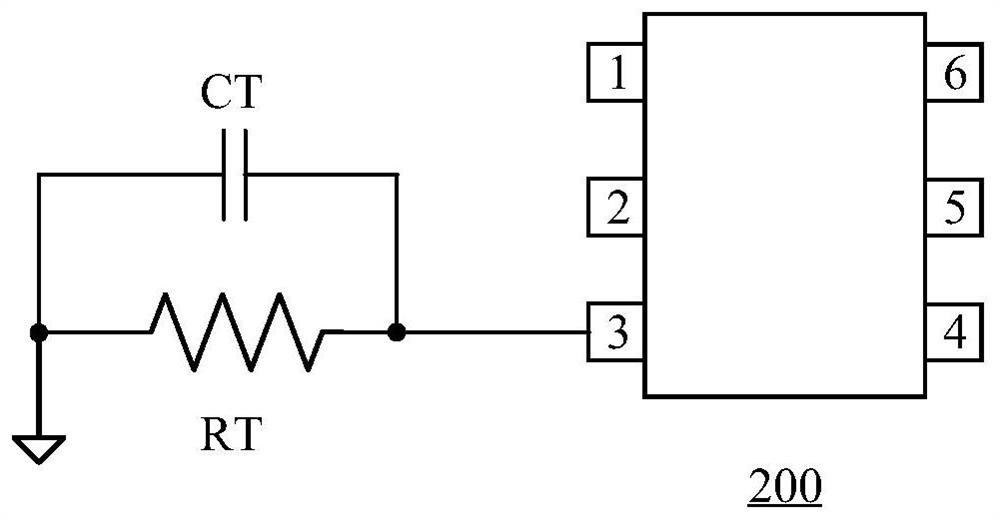
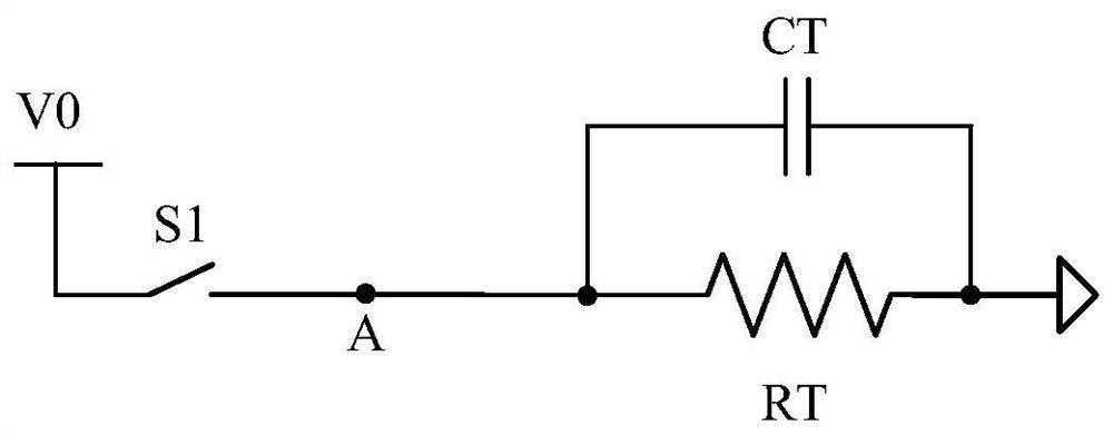
The invention discloses a control chip, a primary side control circuit, a power supply converter and a control method thereof. The power supply converter comprises the primary side control circuit, the primary side control circuit comprises the control chip, and the control chip comprises a third port. The third port is used for respectively connecting a capacitor and a resistor in parallel with the ground, and the output end of the control chip is connected to a switching tube of a primary side circuit of the power supply converter to control the switching state of the switching tube so as torealize the transmission of electric energy from the primary side circuit to a secondary side circuit. The control chip detects the current signal and the voltage signal of the third port in a time-sharing manner, thereby obtaining a first signal representing the capacitance value of the capacitor and a second signal representing the resistance value of the resistor. According to the control chip, the primary side control circuit, the power supply converter and the control method of the power supply converter, multiplexing of the third port of the control chip is achieved, the number of packaging pins of the control chip is reduced, the packaging cost is reduced, and the implementation cost of the primary side control circuit and the power supply converter is reduced.

Description

technical field [0001] The invention relates to the technical field of electronic circuits, in particular to a control chip, a primary side control circuit, a power converter and a control method thereof. Background technique [0002] The power converter generally includes a primary side circuit and a secondary side circuit connected by a transformer, which transmits electric energy from the primary side to the secondary side circuit, wherein the primary side circuit controls the switching state of the switching tubes connected in series on the primary side circuit through the primary side control circuit Realize the transmission of electric energy. [0003] In the flyback power converter based on secondary side feedback, when the primary side control circuit involves more complex functions, it may need to include power input, grounding, output (output pulse width modulation signal to the control terminal of the switch tube), overload Functions such as protection, sampling ...

Claims


Application Information

Patent Timeline
Patent Type & Authority Applications(China)
IPC IPC(8): H02M1/08H02M5/458H02M7/217G05F1/46G05F1/575G05F1/569
CPCG05F1/468G05F1/569G05F1/575H02M1/08H02M5/458H02M7/217
Inventor 金伟祥
Owner SHENZHEN KIWI MICROELECTRONICS CO LTD
Learn More