
Electronic device with a hinge type closing structure

An electrical equipment, hinged technology, applied in the direction of electrical components, circuits or fluid pipelines, transportation and packaging, etc., can solve the problems of separation, inability to achieve positioning and holding current-carrying wires, etc., to achieve a stable locked state, stable engagement, The effect of maintaining stable bonding

Inactive Publication Date: 2010-11-03
SUMITOMO WIRING SYST LTD
View PDF3 Cites 3 Cited by
  • Summary
  • Abstract
  • Description
  • Claims
  • Application Information

AI Technical Summary

Problems solved by technology

However, the latch pawl in the locked position is likely to disengage from the reduced height latch protrusion
This defeats the primary purpose of locating and holding current-carrying wires

Method used


Image

  • Electronic device with a hinge type closing structure
  • Electronic device with a hinge type closing structure
  • Electronic device with a hinge type closing structure

Examples


Embodiment Construction

[0046] Referring now to the accompanying drawings, an embodiment of an electrical appliance having a hinged closing structure according to the present invention will be described below to explain the present invention in more detail.

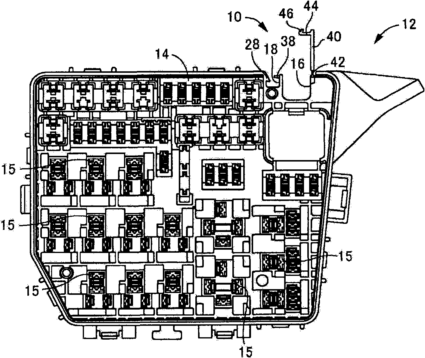
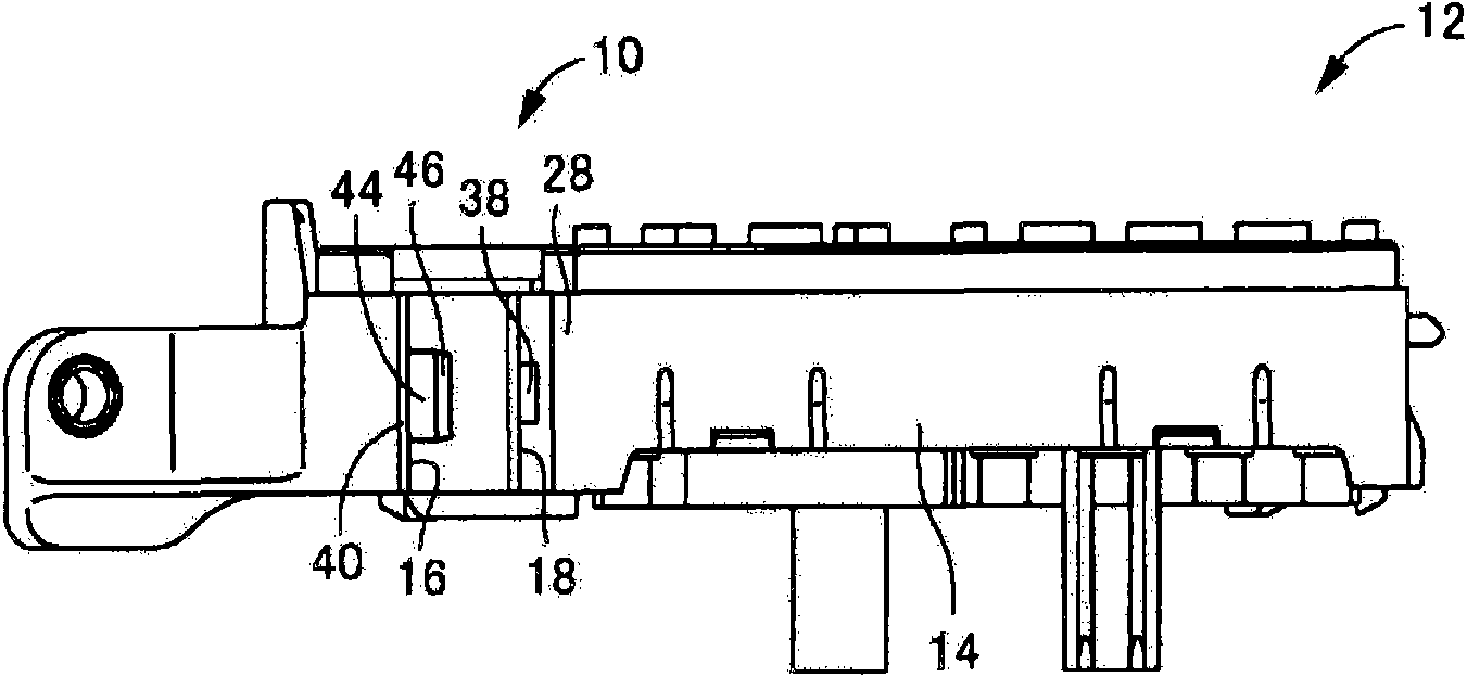
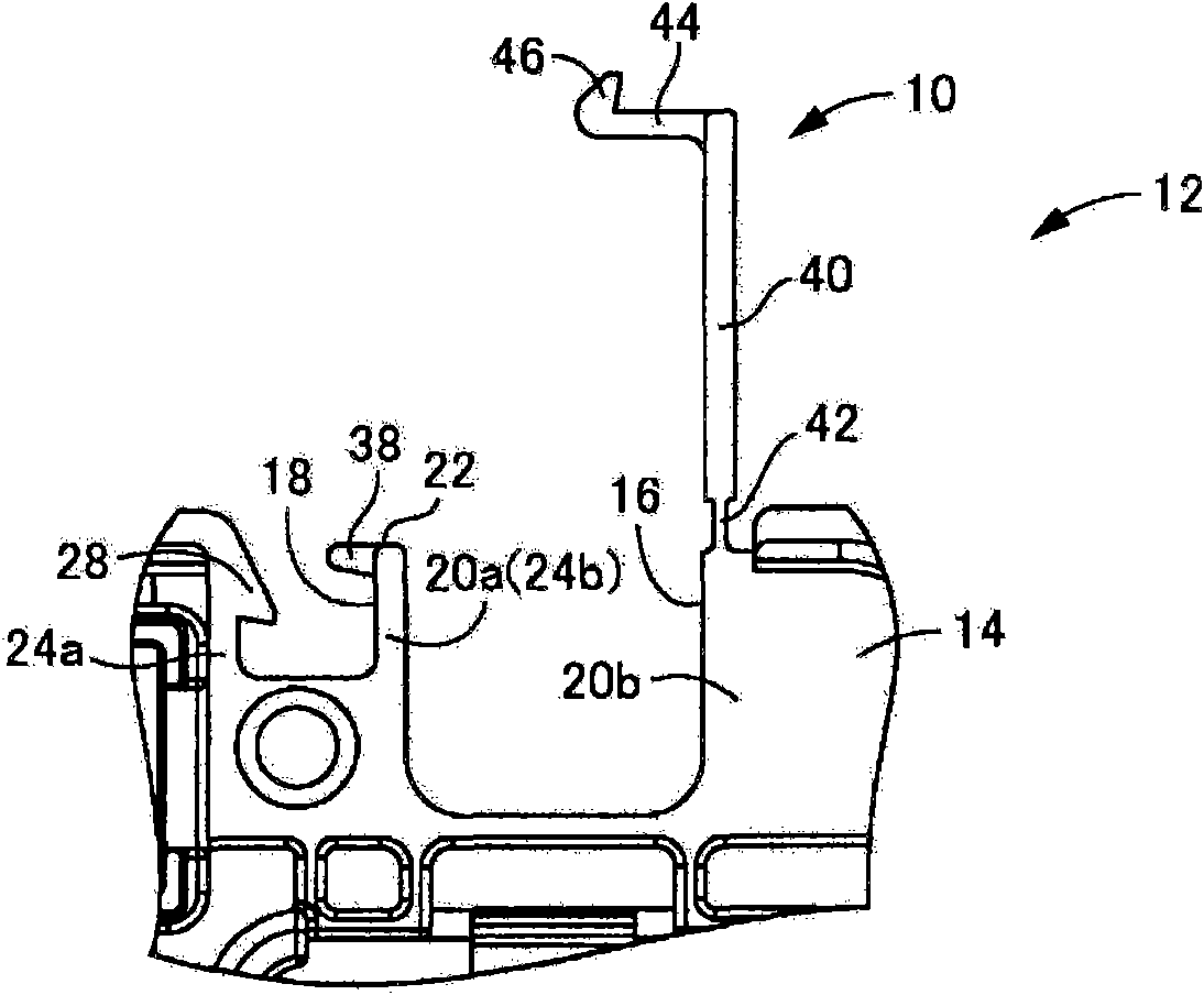
[0047] first, figure 1 with 2 Shown is a main body 14 of an electrical junction box 12 which is an example of an electrical device having a hinged closing structure 10 in an embodiment of the present invention. figure 1 with 2 The hinged closure structure 10 is shown in an open position. The electrical junction box 12 in the present invention may include known conventional units such as junction blocks, fuse boxes or relay boxes. The electrical junction box 12 in this embodiment is a relay box. The main body 14 of the electrical junction box 12 is formed as a substantially rectangular parallelepiped block made of synthetic resin material and provided with a plurality of relay mounting portions 15 .

[0048] Such as image 3 with 4 As sh...


PUM


Abstract

The invention provides an electronic device with a hinge type closing structure, wherein a closing plate (40) is made to cover a housing groove (16) and keep at the stable latching position and arranged at one lateral far end part of the housing groove (16) along the width direction. A locking groove (18) is parallel to the housing groove (16) and arranged at another lateral far end part of the housing groove (16) along the width direction. A locking slice (44) projecting towards the locking groove (18) is arranged at the far-end edge part of the closing plate (40). A latch protrusion part (28) is arranged on the wall inner surface (26a) at the side of the locking groove (18) far away from the housing groove (16). A latching claw (46) engaged with the latch protrusion part (28) is arranged on the locking slice (44).

Description

technical field [0001] The present invention relates to an electrical device to be mounted on a motor vehicle or the like, such as an electrical junction box or a wire harness protector, and more particularly to an electrical device having a closing structure in which current-carrying wires are accommodated and Positioned in the groove covered by the closing plate. Background technique [0002] Heretofore, a plurality of current-carrying wires are arranged in motor vehicles and the like in order to electrically connect various electric devices such as headlights, various motors, and relays. These current-carrying wires are placed and held at given positions in the motor vehicle such that they do not impede the movement of the motor vehicle. [0003] An idea has been proposed to hold the current-carrying wires by utilizing a part of the electrical equipment such as an electrical junction box or a wire harness protector. For example, already in JP 2007-300756A's Figures 2 t...

Claims


Application Information

Patent Timeline
Patent Type & Authority Applications(China)
IPC IPC(8): H02G3/16B60R16/02
CPCH02G3/14H02G3/32
Inventor 水上俊介
Owner SUMITOMO WIRING SYST LTD
Learn More