Eureka AIR delivers breakthrough ideas for toughest innovation challenges, trusted by R&D personnel around the world.

Oil-free lubrication plunger pump

A technology of oil-free lubrication and plunger pumps, which is applied in the direction of pumps, multi-cylinder pumps, liquid displacement machinery, etc., can solve the problems of no heat dissipation device, pollution of the transported liquid, and unfavorable health, so as to achieve convenient and good cleaning. The effect of the cooling effect

Active Publication Date: 2010-11-10
浙江文信机电制造有限公司
View PDF0 Cites 4 Cited by
  • Summary
  • Abstract
  • Description
  • Claims
  • Application Information

AI Technical Summary

Problems solved by technology

Although this structural design achieves the purpose of reducing friction, it also brings some other problems, such as lubricating butter will penetrate into the plunger cavity during work and pollute the delivery liquid, which is especially for the delivery of drinking water , will have adverse effects on people's health. In addition, the replacement and addition of lubricating butter after long-term use is also troublesome.
In addition, even if butter is added for lubrication, the friction will still exist to some extent, which will accumulate a lot of heat after the plunger works for a long time, but in the current structure, there is no special heat dissipation device, only through the valve body itself Spontaneous radiation heat dissipation, the heat dissipation effect is very bad, which will bring a certain burden to the plunger to a certain extent, aggravate wear and tear, and seriously affect the service life of the plunger

Method used


Image

  • Oil-free lubrication plunger pump
  • Oil-free lubrication plunger pump
  • Oil-free lubrication plunger pump

Examples


Embodiment Construction

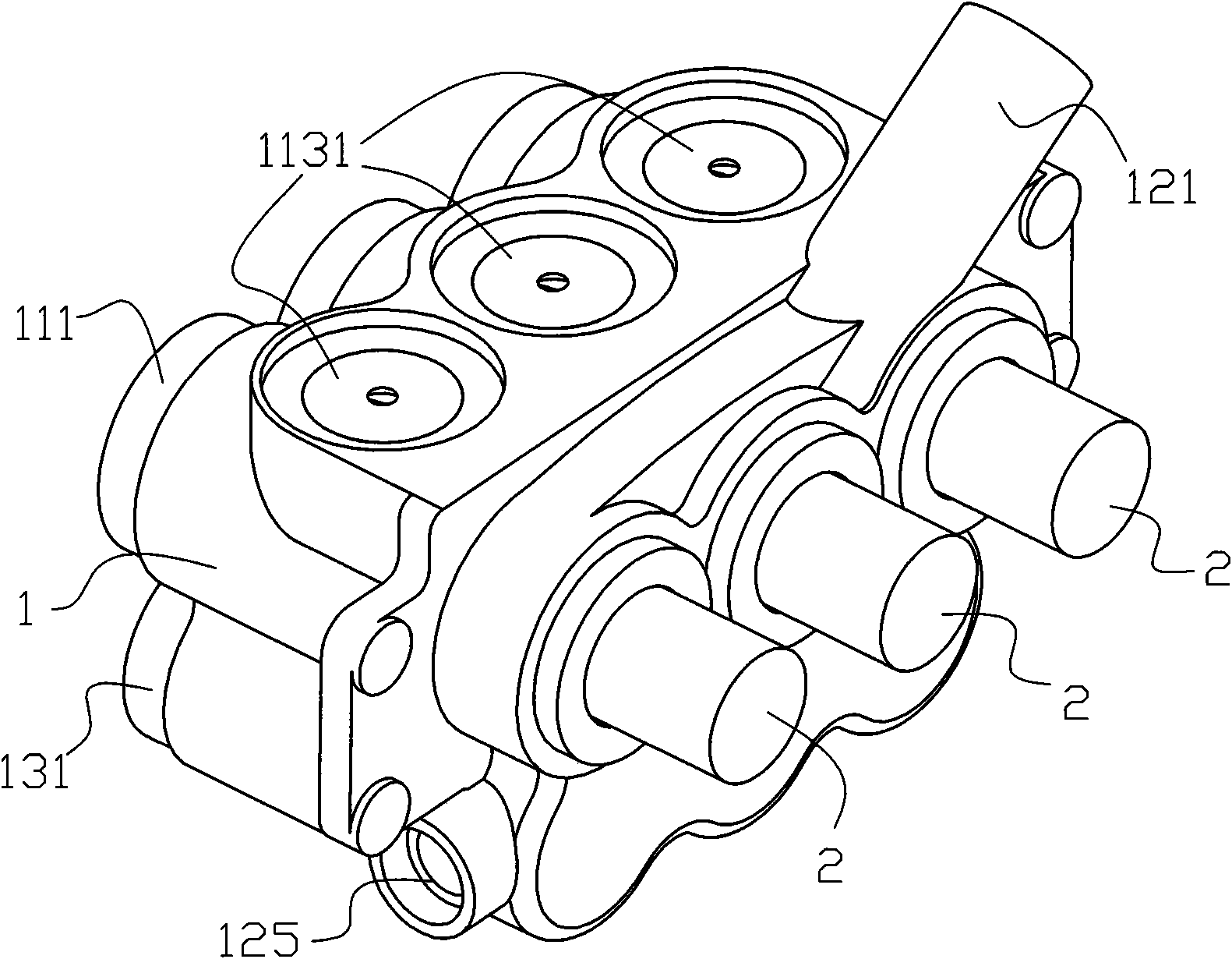
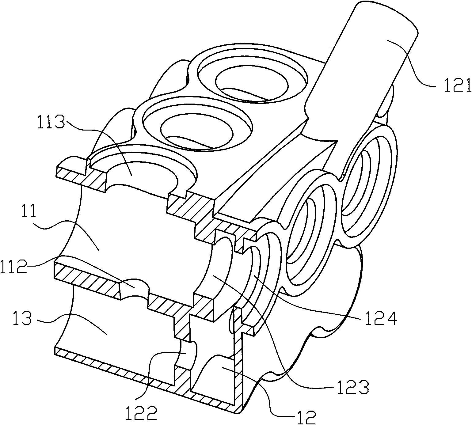
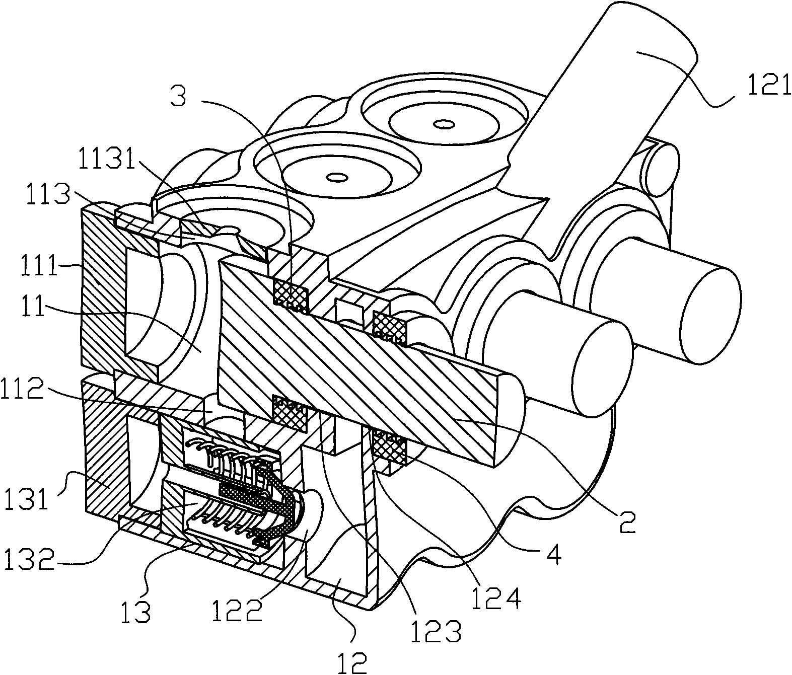
[0016] Such as figure 1 , 2 As shown in and 3, an oil-free lubricated plunger pump includes a valve body 1 and a plunger 2, and the valve body 1 is provided with a plunger chamber 11, a water storage chamber 12 and a water inlet chamber 13.

[0017] The plunger chamber 11 is sealed from the outside world by a plunger cap 111 , and the plunger chamber 11 is provided with a water inlet 112 and a water outlet 113 , wherein a water inlet check valve 1121 is installed on the water inlet 112 .

[0018] The water storage chamber 12 is provided with a water inlet 121 at the top, which is directly used to connect to an external water pipe. The water storage chamber 12 is provided with a communication hole 122 at the bottom to communicate with the water inlet chamber 13. A plunger hole 123 is provided between the cavities 11 , and a plunger installation hole 124 communicating with the outside of the valve body 1 is provided on the outer wall of the water storage chamber 12 .

[0019] ...


PUM


Abstract

The invention discloses an oil-free lubrication plunger pump. The pump comprises a valve body and a plunger, wherein a plunger chamber, a water storage chamber and a water inlet chamber are formed inside the valve body; the plunger chamber is provided with a water inlet and a water outlet; the water outlet is provided with a water outlet one-way valve; the water storage chamber is provided with a water inlet, a communication hole communicated with the water inlet chamber, a plunger hole communicated with the plunger chamber and a plunger mounting hole communicated with the exterior of the valve body; the water inlet chamber is positioned on the lower part of the plunger chamber and communicated with the plunger chamber through the water inlet; the water inlet one-way valve is arranged inside the water inlet chamber; the head of the plunger is positioned inside the plunger chamber; the middle of the plunger is positioned inside the water storage chamber through the plunger hole; and the tail of the plunger is extended out of the valve body through the plunger mounting hole to be connected with a power system. The oil-free lubrication plunger pump solves the problem of an oil lubrication plunger pump and has the characteristics of convenient use, good heat dissipation effect and cleanness and no pollution; and moreover, the plunger of the oil-free lubrication plunger pump performs lubrication and temperature reduction directly through conveying liquid.

Description

technical field [0001] The invention relates to a plunger pump, in particular to an oil-free lubricated plunger pump. Background technique [0002] Compared with the centrifugal pump, the plunger pump has the characteristics of reliable operation, large flow rate and high pressure, and it is widely used in the transportation of drinking water in high-rise buildings. In the structure of the plunger pump, take the single plunger system of the plunger pump as an example, which includes a plunger chamber and a reciprocating axially movable plunger. The plunger chamber is provided with a water inlet and a water inlet. And the water inlet is provided with a water inlet one-way valve, and the water outlet is provided with a water outlet one-way valve. When the plunger moves in one direction, there is a negative pressure in the cavity. At this time, the water inlet one-way valve is opened and the water outlet one-way valve is closed. , the liquid is sucked into the chamber, and whe...

Claims


Application Information

Patent Timeline
IPC IPC(8): F04B1/16
Inventor 阮孟照
Owner 浙江文信机电制造有限公司
Why Eureka
Eureka Blog
Learn More