
Optical fiber used for eliminating laser coherence

A coherent and optical fiber technology, applied in the laser field, can solve problems such as inconvenient maintenance, complex device structure, and many components

Inactive Publication Date: 2010-11-10
PHOEBUS VISION OPTO ELECTRONICS TECH +1
View PDF4 Cites 4 Cited by
  • Summary
  • Abstract
  • Description
  • Claims
  • Application Information

AI Technical Summary

Problems solved by technology

[0004] In the prior art, one way to reduce laser coherence and thus reduce laser speckle is to vibrate the medium transmitting the laser, for example, using a vibration motor to vibrate the fiber bundle, and the coherence of the laser at the output end of the fiber bundle can be reduced to a certain extent, but Such a device has a complex structure, many parts, inconvenient maintenance, and it is a dynamic device that operates with a lot of noise

Method used


Image

  • Optical fiber used for eliminating laser coherence
  • Optical fiber used for eliminating laser coherence
  • Optical fiber used for eliminating laser coherence

Examples


Embodiment 1

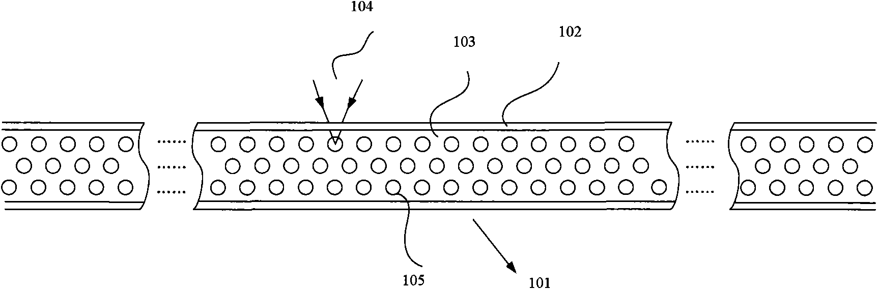
[0021] figure 1 The structure and the manufacturing principle of the optical fiber 101 with the region of non-uniform refractive index according to the embodiment of the present invention are exemplarily shown. Such as figure 1 As shown, the optical fiber 101 is composed of an outer cladding (cladding) 102 and an inner core (core) 103. The cladding 102 wraps the core 103 to form a concentric cylindrical shape, and the core 103 is distributed with multiple refractive indices. Uneven area 105 . The optical fiber 101 is a silica optical fiber, that is, the core 103 of the optical fiber 101 is made of silica. On the outside of the cladding 102, there is usually a resin protective layer for strengthening the strength, figure 1 In order to clarify the illustration, the resin protective layer is not drawn. In the prior art, the core refractive index of an ordinary optical fiber is uniform and greater than the refractive index of the cladding 102, so that the laser propagates in a...


PUM

PropertyMeasurementUnit
Sizeaaaaaaaaaa

Abstract

The invention provides an optical fiber used for eliminating laser coherence, which comprises a cladding and a fiber core. The cladding is wound on the outer side of the fiber core; and a plurality of areas with nonuniform refractive indexes are distributed in the fiber core. The optical fiber has the advantages of simple structure, easy implementation, adoption of a static modulation mode, small noise, and long service life. Meanwhile, although common laser display equipment needs field uniformizing devices, the field uniformizing devices can be saved because the optical fiber used for eliminating laser coherence can realize the field uniformizing function; therefore, the structure of the laser display equipment is more compact.

Description

technical field [0001] The invention relates to the field of lasers, in particular to an optical fiber for eliminating laser coherence. Background technique [0002] Generally, lasers are monochromatic and directional. Taking advantage of this characteristic, lasers are used in various fields such as optical communication, precision instrument use or display, etc. Among them, research on display systems and display methods using laser light as a light source is particularly active. [0003] However, when a laser is used as a light source for image display, laser speckle (also called speckle noise) occurs due to the better coherence of the laser. Laser speckle is a phenomenon that randomly generates local uneven brightness on the screen. This laser speckle will significantly reduce the image display quality, so reducing laser speckle is an important task. [0004] In the prior art, one way to reduce laser coherence and thus reduce laser speckle is to vibrate the medium tra...

Claims


Application Information

Patent Timeline
IPC IPC(8): G02B6/02G02B26/08G03B21/00
Inventor 毕勇成华郑光王斌亓岩
Owner PHOEBUS VISION OPTO ELECTRONICS TECH
Learn More