
Wireless positioning system

A technology of wireless positioning system and wireless beacon, which is applied in the field of wireless positioning system in the mine, can solve the problems of increased power consumption, the inability of the system to realize multi-base station positioning, interruption of communication functions, etc., so as to reduce the number of reports and reduce the amount of deployment , to maintain the effect of continuity

Inactive Publication Date: 2010-11-10
上海中兴易联通讯股份有限公司
View PDF1 Cites 21 Cited by
  • Summary
  • Abstract
  • Description
  • Claims
  • Application Information

AI Technical Summary

Problems solved by technology

However, PHS and Wifi will be limited due to the base station capacity when there are many people at the same time.
And when the positioning communication terminal detects the field strength of the surrounding base stations, it needs to leave the network temporarily, and the communication function is interrupted, which has hidden dangers to production management and safety management
At the same time, in the continuous positioning state, the power consumption of the positioning communication terminal increases, and the working time of the battery is limited
[0007] The Chinese patent application No. 200710119139.8 discloses an underground positioning system and method. Although a wireless beacon is used, the beacon only broadcasts the node identification, and the accuracy cannot be guaranteed during the positioning process, and the system cannot realize multi-base station positioning.
The positioning terminals are not synchronized in time. When the number of terminals is large, the wireless channel is frequently occupied
In addition, since its wireless communication base station ("receiving node" in the text) participates in positioning detection and other related actions, it is bound to affect the communication function or increase power consumption due to the detection of the field strength of the surrounding base stations.

Method used


Image

  • Wireless positioning system
  • Wireless positioning system
  • Wireless positioning system

Examples


Embodiment Construction

[0024] Embodiments of the present invention are described below through specific examples, and those skilled in the art can easily understand other advantages and effects of the present invention from the content disclosed in this specification. The present invention can also be implemented or applied through other different specific examples, and various modifications and changes can be made to the details in this specification based on different viewpoints and applications without departing from the purpose of the present invention.

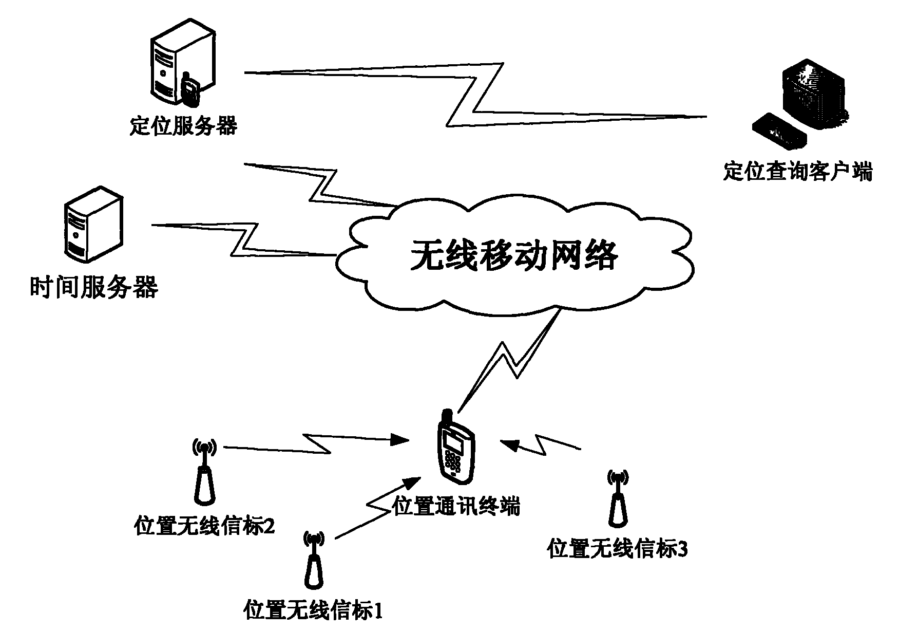
[0025] A wireless positioning system of the present invention is applied in the field of wireless positioning, and the following mainly takes the application in underground positioning as an example for detailed description.

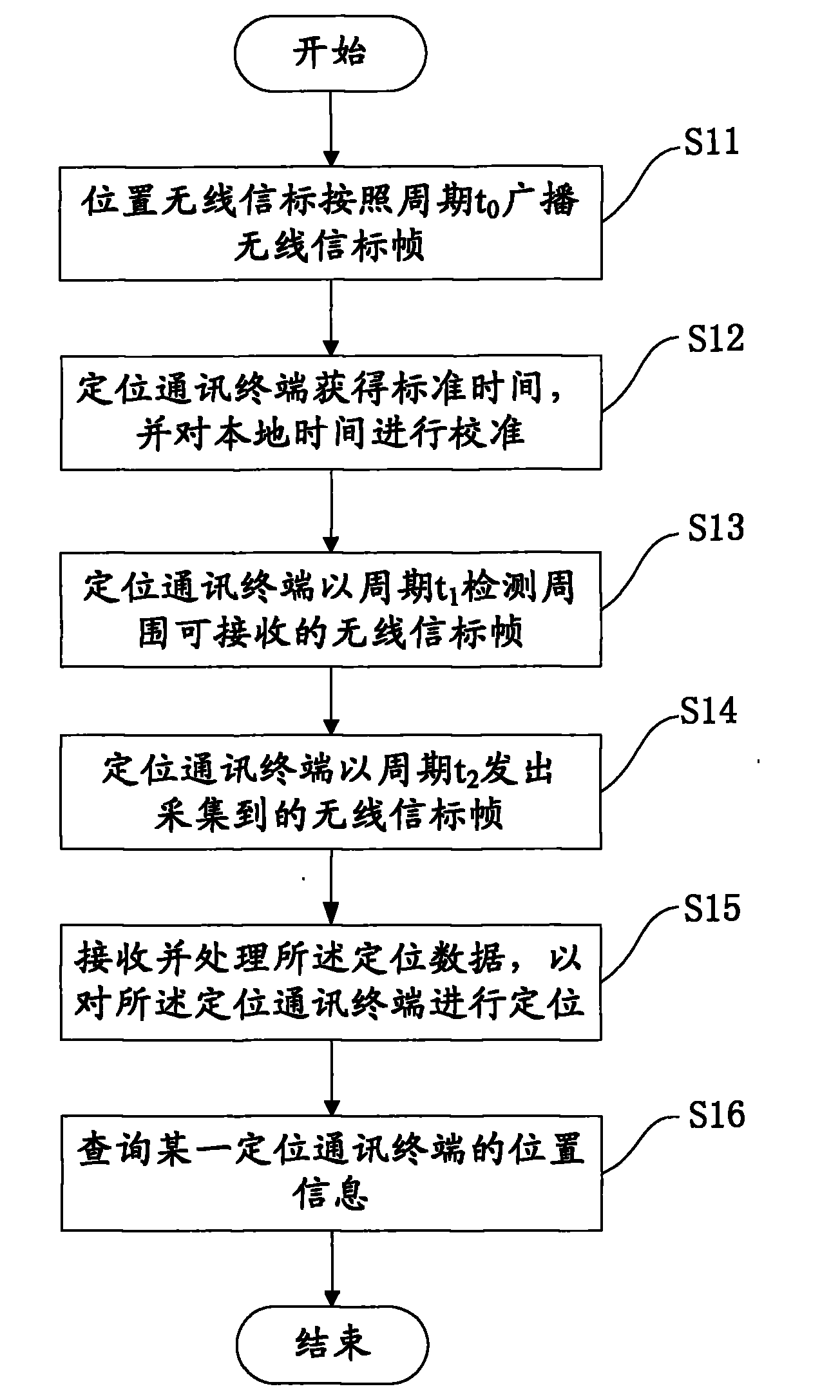
[0026] The invention proposes a wireless positioning system, which is a positioning system based on a position wireless beacon and a wireless communication network. The locating method of the present invention combines th...


PUM


Abstract

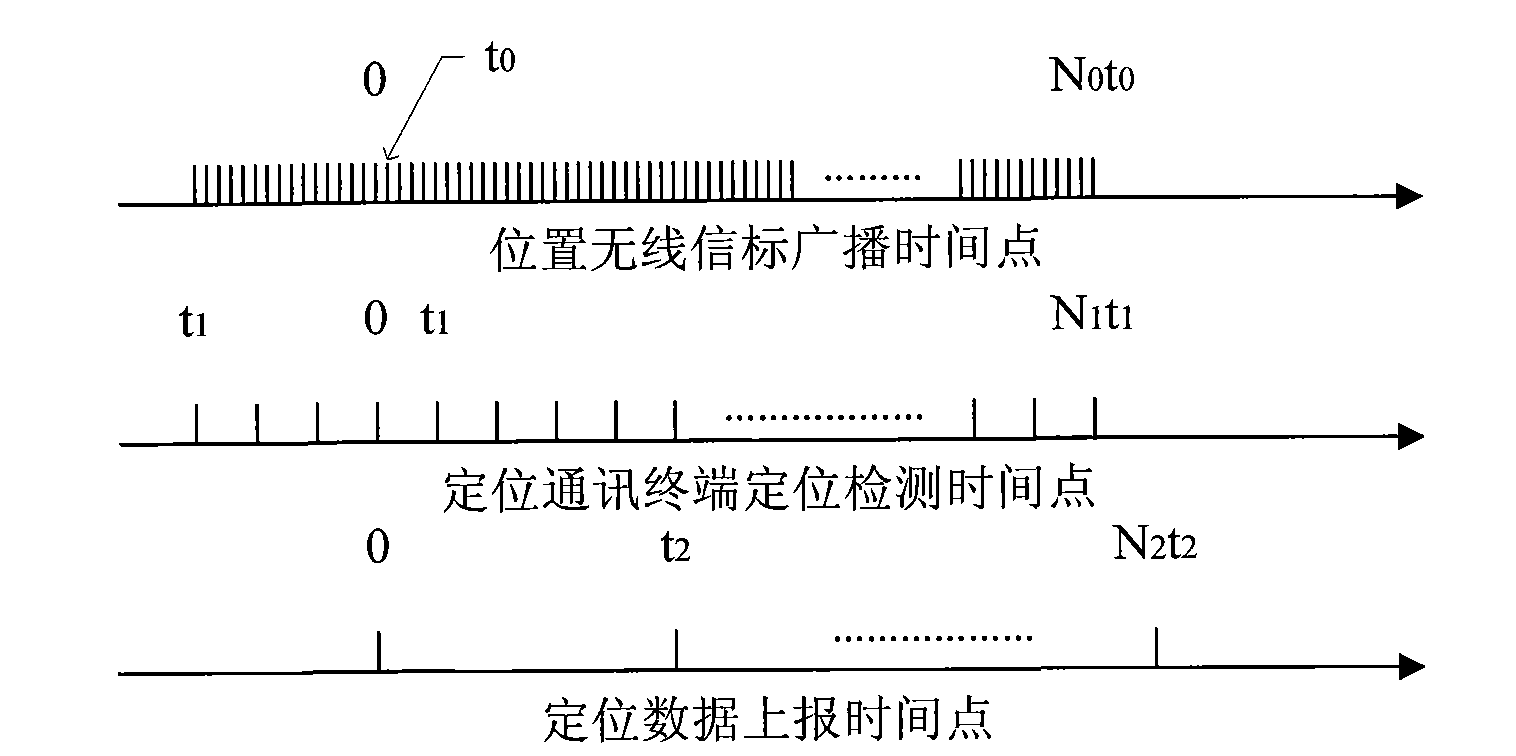
The invention discloses a wireless positioning system which is technology based on wireless position beacons and a wireless communication network. The system comprises the wireless position beacons, a positioning communication terminal, a time server, the wireless communication network and a positioning server. The positioning process is as follows: detecting the wireless beacon frames emitted by the wireless position beacons in the place by the positioning communication terminal and sending the detected results to the positioning server and computing the position of the positioning communication terminal by the positioning server according to the positions of the wireless position beacons stored in the positioning server. The system has the following advantages: the whole system realizes the balance of capacity, power consumption, efficiency and the like; the wireless position beacons only need to send signals periodically and have simple structures; the positioning communication terminal does not need to break away from the network temporarily, can maintain continuity of communications and simultaneously reduce battery consumption and the deployment amount of mobile base stations; a time server is used for unifying the terminal time so that the terminal can delay reporting and not lose the positioning information; and simultaneously the times of reporting can be reduced.

Description

technical field [0001] The invention relates to the technical field of wireless positioning, in particular to a system for performing wireless positioning underground. Background technique [0002] Communication technology is changing with each passing day, especially wireless communication technology, which is particularly important in today's period of rapid development of the information industry. The application of wireless communication technology has naturally become an important direction of scientific and technological development. Among them, the use of wireless communication for positioning is an important application now and even in the future. [0003] For example, in the process of underground operations, in the exploration process, etc., positioning is required. However, in the above-mentioned special environment, no matter the technology used or the maintenance work in the future, many difficulties will often be encountered, and The use of wireless communicat...

Claims


Application Information

Patent Timeline
IPC IPC(8): H04W64/00H04W88/18G06K7/00
CPCY02B60/50Y02D30/70
Inventor 雷剑虹肖长春
Owner 上海中兴易联通讯股份有限公司
Learn More