
Carbonation depth detector

A carbonization depth and detection instrument technology, applied in the direction of measuring instrument components, instruments, measuring devices, etc., can solve the problems of difficulty in determining the carbonization front, poor light in the hole, difficult positioning, etc., to eliminate insufficient light in deep holes and direct readings , Measuring the effect of quick

Inactive Publication Date: 2010-11-17
ZHEJIANG UNIV
View PDF9 Cites 14 Cited by
  • Summary
  • Abstract
  • Description
  • Claims
  • Application Information

AI Technical Summary

Problems solved by technology

However, when the carbonation depth of concrete is relatively large, such as on-site concrete carbonation is more serious, especially when the carbonation depth of concrete is studied in the laboratory and the concrete components are not allowed to be damaged, it is difficult or impossible to determine the boundary between the carbonized area and the non-carbonated area by sight. The above method is difficult to obtain accurate carbonation depth value, which makes the determination of concrete strength and durability index by rebound very inaccurate
[0003] At present, there are existing ruler-type and pen-type carbonation depth measurement patents for measuring the carbonation depth of concrete. The measurement depth is less than 10mm, which cannot meet the measurement of concrete components with a large carbonation depth; The measurement depth has been improved, but the measurement principle is the same as that of the ruler-type and pen-type carbonization depth measuring instruments, which mainly rely on the eyes to distinguish the boundary between the carbonized area and the non-carbonized area. boundary, and the light in the hole is poor at this time, making it more difficult to determine the carbonization front
Using current instruments to accurately measure cement-based material components with a large carbonization depth, only the components are destroyed, but this is not allowed in actual engineering or component tests in some laboratories

Method used


Image

  • Carbonation depth detector
  • Carbonation depth detector
  • Carbonation depth detector

Examples


Embodiment Construction

[0012] The measurement of carbonization depth is mainly composed of image magnification and imaging module and measurement module. The image magnification and imaging module mainly includes several parts such as image magnification, image acquisition and transmission, and image display. The image magnification function is mainly realized by an optical lens or a microscope lens with a magnification function; image acquisition and transmission are mainly realized by lighting sources, cameras, signal cables, and image acquisition and processing chips; image display is the acquisition and processing of video signals Input the video monitor to display the captured image information in real time. Through the image magnification and imaging module, the color change image of the carbonized area and the non-carbonized area of ​​cement-based materials such as concrete sprayed with phenolphthalein can be clearly displayed on the video display screen. The carbonization depth measurement ...


PUM


Abstract

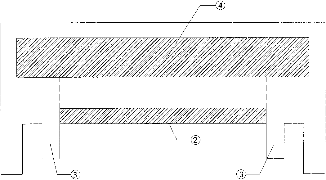
The invention discloses a carbonation depth detector. The carbonation depth detector comprises a staff, a microscope, a lighting source, a camera, a detector housing, a bulge on the end of the staff, a precision gear, a signal cable, a current supply cable, an image collecting and processing chip, a video display, a roller with a spring, a power switch, a power work indicating lamp, a diode and a camera power supply module. The carbonation depth detector can clearly and truly display the color change of concrete after phenolphthalein is sprayed on concrete; and the carbonation dividing line can be accurately found through the displayed image video, thus avoiding the error caused by oblique visual observation. Therefore, the measurement is fast and the operation is simple.

Description

technical field [0001] The invention relates to a carbonization depth detector used for testing the durability of cement-based materials and structures, in particular to a detection instrument which can accurately determine the carbonization front and measure the carbonization depth through graphic amplification and imaging. Background technique [0002] Carbonation depth is an important index to measure the strength and durability of service concrete. At present, the drilling method is generally used in engineering testing and existing specifications, that is, drilling holes on the detection object with an electric drill, and then spraying the concrete around the drilling hole with phenolphthalein to distinguish the carbonized area and the non-carbonated area of ​​the concrete, that is, to find out the carbonized area. Edge or carbonization boundary, and then measure with a ruler or a vernier caliper. This method is more feasible when the carbonization depth is small and t...

Claims


Application Information

Patent Timeline
IPC IPC(8): G01B11/22G01D11/28G01N33/38
Inventor 孙晓燕王海龙
Owner ZHEJIANG UNIV
Learn More