Method for measuring target azimuth by single-beam mechanical scanning radar

A technology of mechanical scanning and target orientation, which is applied in the fields of communication and radar, can solve the problems of large amount of computation and low accuracy of angle measurement, achieve the effects of small amount of computation, flexible processing, and improvement of measurement accuracy

Inactive Publication Date: 2010-11-17
HARBIN INST OF TECH
View PDF3 Cites 29 Cited by
  • Summary
  • Abstract
  • Description
  • Claims
  • Application Information

AI Technical Summary

Problems solved by technology

[0005] In order to solve the problem of low angle measurement accuracy and large amount of computation of the existing single-beam mec...

Method used


Image

  • Method for measuring target azimuth by single-beam mechanical scanning radar
  • Method for measuring target azimuth by single-beam mechanical scanning radar
  • Method for measuring target azimuth by single-beam mechanical scanning radar

Examples


specific Embodiment approach 1

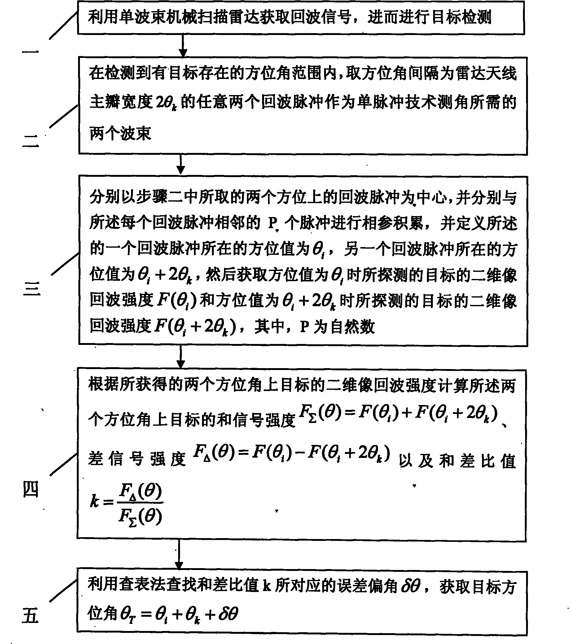
[0014] Specific implementation mode one: according to the instructions attached figure 1 Specifically illustrate the present embodiment, a kind of method for single-beam mechanical scanning radar measuring target azimuth described in the present embodiment, it comprises the following steps:

[0015] Step 1: Use the single-beam mechanical scanning radar to obtain the echo signal, and then perform target detection;

[0016] Step 2: Within the azimuth range where the target is detected, take the azimuth interval as the radar antenna main lobe width 2θ k Any two echo pulses of any two pulses are used as the two beams required for angle measurement by monopulse technology;

[0017] Step 3: Take the echo pulses in the two azimuths taken in step 2 as the center, and perform coherent accumulation with the P pulses adjacent to each echo pulse, and define the echo pulse The azimuth value of the wave pulse is θ i , the azimuth value of the other echo pulse is θ i +2θ k , and then ge...

specific Embodiment approach 2

[0020] Specific embodiment 2: This embodiment is a further description of specific embodiment 1. In specific embodiment 1, in step 2, the radar antenna is a receiving antenna, and the main lobe width of the radar antenna is 2θ k = θ 0.5 , where θ 0.5 is the width of the main lobe at the half-power point of the antenna in one-way.

specific Embodiment approach 3

[0021] Specific embodiment three: This embodiment is a further description of specific embodiment one. In the specific embodiment one, in step two, the radar antenna is a common antenna for transmitting and receiving, and the main lobe width of the radar antenna is Among them, θ 0.5 is the width of the main lobe at the half-power point of the antenna in one-way.

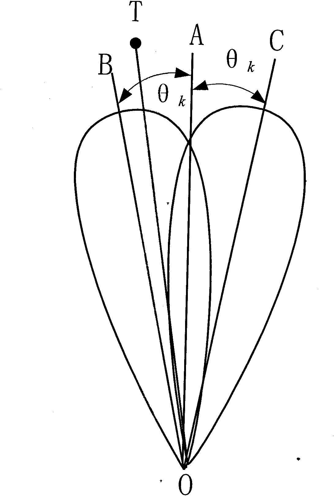
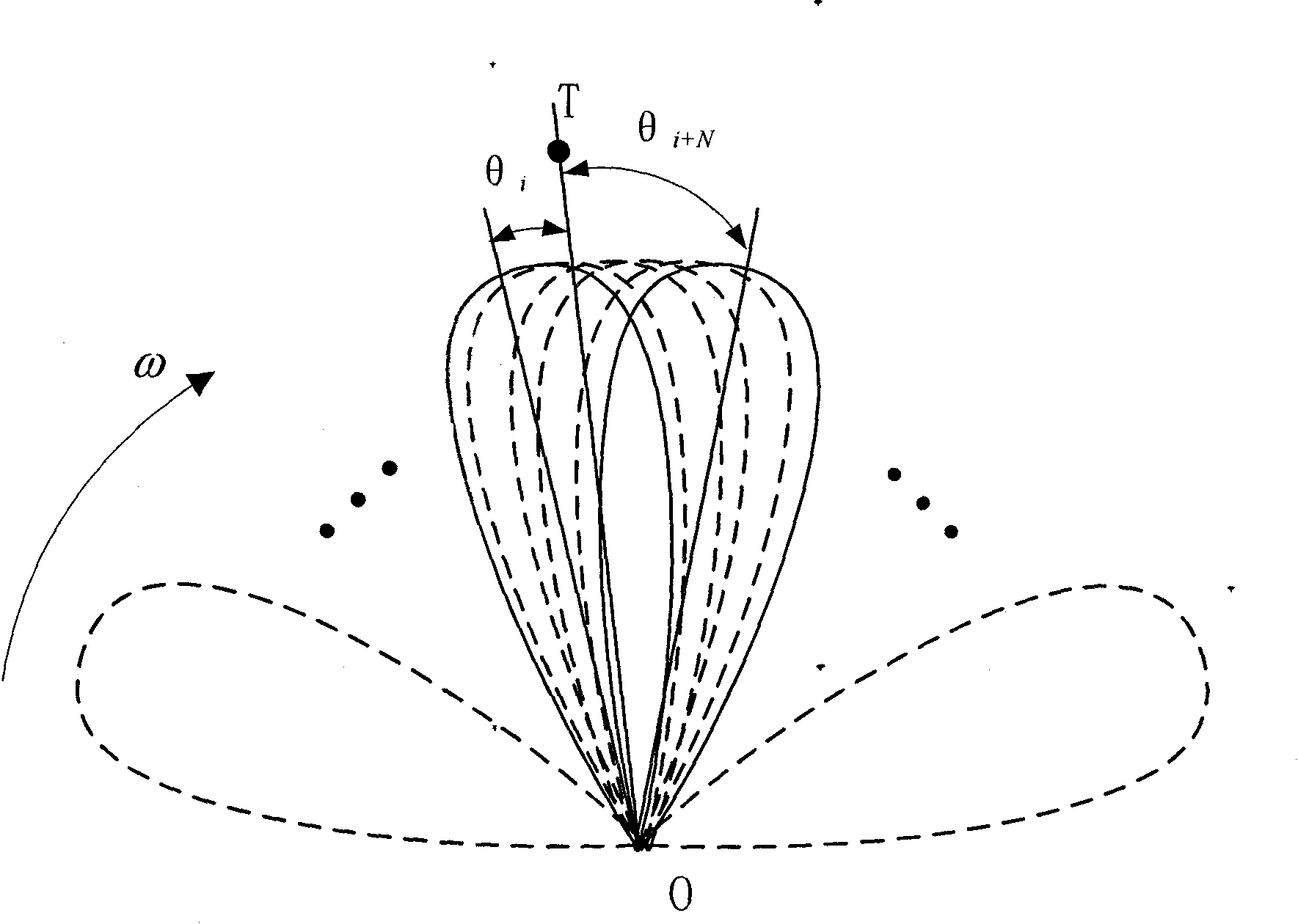
[0022] The implementation scheme of this embodiment is proposed based on the monopulse technology, and a higher signal-to-noise ratio can be obtained by using coherent accumulation, so as to facilitate detection of target information. figure 2 It is a schematic diagram of the principle of simultaneous lobe monopulse technology, which uses two identical and partially overlapping beams, where OA is the equal signal axis, and the corresponding azimuth is θ 0 , OB and OC are the antenna axes of the two beams respectively, and the included angles between them and the equal-signal axis OA are both θ k . The azimuth ...


PUM


Abstract

The invention discloses a method for measuring a target azimuth by single-beam mechanical scanning radar, which relates to the technical field of radar and communication and solves the problems of low angle measurement precision and large operation amount of the conventional single-beam mechanical scanning radar. The method comprises the following steps of: acquiring echo signals by using the single-beam mechanical scanning radar, then performing phase coherence accumulation on the acquired echo signals to acquire a higher signal detection signal-to-noise ratio, taking an azimuth interval of any two echo pulses of a main lobe width of a radar antenna as two beams required for measuring an angle by the single-pulse technology after target information is detected, then calculating two-dimensional images, sum signal intensity and difference signal intensity of a target on two azimuths, and further calculating a sum-to-difference ratio k so as to acquire a target error deflection angle delta theta, wherein the target azimuth theta T is equal to theta i + theta k + delta theta. The method is suitable for radar angle measurement.

Description

technical field [0001] The invention relates to the technical fields of radar and communication, in particular to a method for measuring the azimuth angle of a target by a single-beam mechanical scanning radar. Background technique [0002] Single-beam mechanical scanning radar is often used in the detection channel of the new imaging radar inverse synthetic aperture radar (ISAR), search radar and surround-view radar. The traditional angle measurement method uses the amplitude method, including the maximum signal method and the threshold detection method. The maximum signal method is to compare the echo strength one by one, and take the maximum value of the amplitude as the center of the azimuth estimation. The threshold detection method is an implementation method of the maximum signal method for automatic angle measurement. The basic idea is to use the symmetry of the antenna, and use the average value of the two azimuths when the echo signal is higher and lower than the d...

Claims


Application Information

Patent Timeline
IPC IPC(8): G01S13/46G01S13/90G01S7/41
Inventor 谢俊好冯晓东袁业术李绍滨
Owner HARBIN INST OF TECH
Why Eureka
Try Eureka